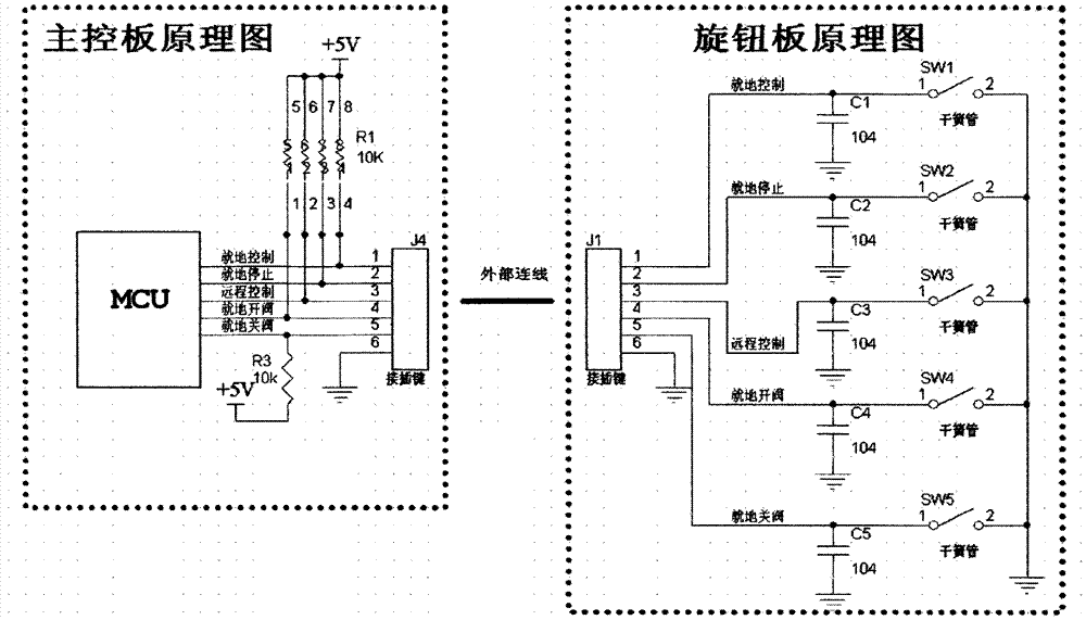
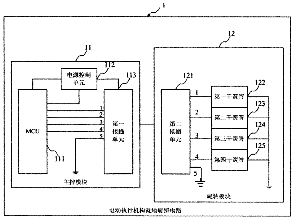
Circuit of in-place rotary knobs of electric actuator

A technology of electric actuators and knobs, applied in computer control, instruments, simulators, etc., can solve the problems of inconvenient installation, production and maintenance, low detection capability, and high material costs, so as to reduce installation and material costs, and reduce external connections. line, the effect of improving reliability

Active Publication Date: 2014-10-29
安徽费斯威尔流体智控有限责任公司 +1
View PDF6 Cites 0 Cited by
  • Summary
  • Abstract
  • Description
  • Claims
  • Application Information

AI Technical Summary

Problems solved by technology

[0008] In view of the above-mentioned shortcomings of the prior art, the purpose of the present invention is to provide a local knob circuit of the electric actuator, which is used to solve the problems of high material cost, inconvenient installation, production and maintenance in the prior art, and reliability during use and wear. Low reliability, many fault points, and low detection ability

Method used


Image

  • Circuit of in-place rotary knobs of electric actuator
  • Circuit of in-place rotary knobs of electric actuator
  • Circuit of in-place rotary knobs of electric actuator

Examples


Embodiment Construction

[0039] Embodiments of the present invention are described below through specific examples, and those skilled in the art can easily understand other advantages and effects of the present invention from the content disclosed in this specification. The present invention can also be implemented or applied through other different specific implementation modes, and various modifications or changes can be made to the details in this specification based on different viewpoints and applications without departing from the spirit of the present invention. It should be noted that, in the case of no conflict, the following embodiments and features in the embodiments can be combined with each other.

[0040] It should be noted that the diagrams provided in the following embodiments are only schematically illustrating the basic ideas of the present invention, and only the components related to the present invention are shown in the diagrams rather than the number, shape and shape of the compo...


PUM


Abstract

The invention provides a circuit of in-pace rotary knobs of an electric actuator. The circuit of the in-pace rotary knobs of the electric actuator comprises a casing, a main control module and a rotary knob module, wherein the outside of the casing is provided with the in-pace control rotary knob and the in-pace operation rotary knob, and the in-pace control rotary knob and the in-pace operation rotary knob are both provided with magnets; the main control module comprises a micro-control unit, a power supply control unit controlled by the micro-control unit and a first plug-in module with 5 ports, and the power supply control unit is provided with a first end, a second end and a third end; the rotary knob module is arranged inside the casing and is connected with the main control module through an external connecting wire, the rotary module is provided with a second plug-in unit with a first port, a second port, a third port, a forth port and a fifth port, the first port, the second port, the third port and the forth port are respectively connected with a reed switch used for sensing the position of the magnets. The circuit of the in-pace rotary knobs of the electric actuator can improve detection means and judging functions of an electric actuator reduce installation and material costs and probability of fault points and improve reliability of the control circuit.

Description

technical field [0001] The invention relates to a control circuit, in particular to a local knob circuit of an electric actuator. Background technique [0002] In order to improve the sealing and safety of the intelligent electric actuator to achieve dustproof, waterproof and anti-riot (IP68, ExiaIICT4), the local knob of the electric actuator often adopts a non-invasive design, which does not destroy the integrity of the front cover of the electric actuator. Magnetic induction path to achieve local control and switch valve. The local knob of the electric actuator is composed of two knobs, the local control knob and the local operation knob. The local control knob can switch between local control function, local stop function and remote control function through the knob. The local operation knob can be switched to the function of opening the valve locally and closing the valve locally through the knob. [0003] In the prior art, a magnet is respectively installed on the l...

Claims


Application Information

Patent Timeline
IPC IPC(8): G05B19/042
Inventor 梁其顺戴荣林梁天
Owner 安徽费斯威尔流体智控有限责任公司
Why Eureka
Try Eureka