Computer-generated holograms

A computational holography, thin flat sheet technology, applied in diffraction grating and other directions, can solve problems such as difficulty in reaching spectroscopic devices, and achieve the effect of convenient processing

Inactive Publication Date: 2012-04-25
SUZHOU UNIV
View PDF3 Cites 0 Cited by
  • Summary
  • Abstract
  • Description
  • Claims
  • Application Information

AI Technical Summary

Problems solved by technology

[0002] In many applications, it is necessary to use two beams of coherent light with equal energy. In many cases, the angles of the two beams of light required are too close, and coherent light is required, so only one beam of light can be obtained by splitting light. The traditional It is difficult for optical splitting devices to achieve this effect

Method used


Image

  • Computer-generated holograms
  • Computer-generated holograms
  • Computer-generated holograms

Examples


Embodiment 1

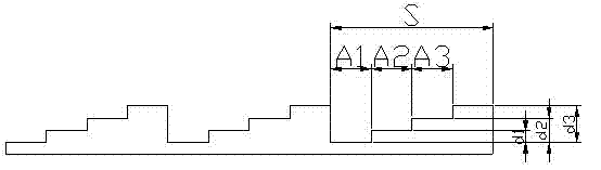
[0019] Embodiment one: see figure 1 and figure 2 As shown, a computational holographic sheet is composed of repeated arrangement of phase-type microstructure units S arranged on a thin flat sheet, and each phase-type microstructure unit S contains four platforms arranged in order from low to high, and each The platforms constitute a phase, and the width of each phase platform (A1, A2, A3) is the phase width, which is 1 / 4 of the total width of the phase microstructure unit. Taking the lowest platform as the relative zero point, the phase heights of the other three phase platforms are d1, d2, and d3 respectively, satisfying d3-d2=d1.

[0020] In this embodiment, the phase height d1 is , .

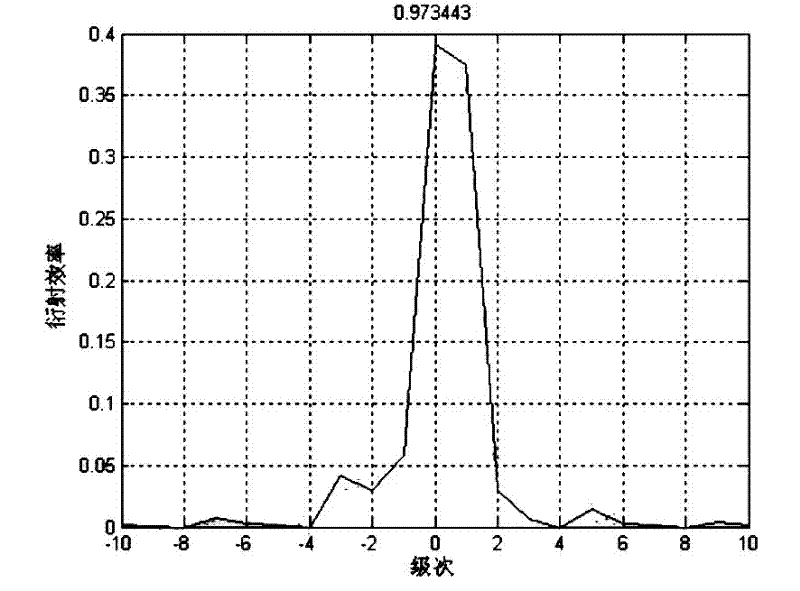
[0021] The proportion distribution of different energy level energy in this embodiment to the total energy is shown in the attached figure 2 As shown, it can be seen from the figure that the energy of the diffraction energy level 0 and 1 is equal (the error does not exceed 5%), which...

Embodiment 2

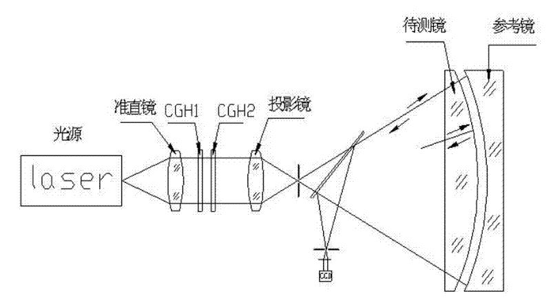
[0022] Embodiment 2: The computational hologram of Embodiment 1 is applied to an example of dual CGH detection of off-axis convex aspheric surfaces. The optical path structure of this embodiment is as image 3 As shown, the specific optical path analysis can be found in the appendix Figure 4 , the +1 level (or -1 level) light generated by CGH1 is split by CGH2 and divided into two beams, one of which is the reference light, which is reflected by the reference surface, and one is the detection light, which is reflected by the lens to be tested. Then the two light beams are combined and imaged by interference on the CCD. Through the identification of interference fringes, analyze and judge the mirror error.

[0023] From Figure 4 It can be known from the above that to make the image contrast on the CCD very good, it is required that the 0-level and 1-level energies of the emitted light of CGH2 are equal. Therefore, the computational hologram of the first embodiment is used...


PUM


Abstract

The invention discloses computer-generated holograms, which are formed by arranging phase microstructural units repeatedly on a thin plain film. The computer-generated holograms are characterized in that: each phase microstructural unit contains four platforms which are arranged sequentially from bottom to top; each platform forms a phase; the width of each phase platform, namely the phase width,is 1 / 4 of the total width of each phase microstructural unit; the lowest platform is taken as a zero phase, and the phase heights of the other three high platforms are d1, d2 and d3 respectively, wherein d3-d2 is equal to d1. The computer-generated holograms of which the energy of 0 stage and the energy of 1 stage are equal are obtained, so the computer-generated holograms can be applied on occasions when light splitting devices of which different energy levels have equal energy are needed for testing off-axis convex aspheric surfaces and the like.

Description

technical field [0001] The invention relates to a light splitting device, in particular to a light splitting device for splitting a beam of light into two beams of equal energy. Background technique [0002] In many applications, it is necessary to use two beams of coherent light with equal energy. In many cases, the required angles of the two beams of light are too close, and coherent light needs to be used, so only one beam of light can be obtained by splitting. The traditional It is difficult for optical splitting devices to achieve this effect. For example, when using double CGH (computational holography) sheets to inspect off-axis convex aspheric surfaces, it is necessary to use a spectroscopic device with different energy levels and equal energy, and the required 0-level and 1-level energies are almost equal (the error is within 5% Inner), and the energy of other energy levels accounts for no more than 15% of the energy of level 0 or level 1, so that the contrast of t...

Claims


Application Information

Patent Timeline
Patent Type & Authority Patents(China)
IPC IPC(8): G02B5/18
Inventor 任建锋郭培基
Owner SUZHOU UNIV
Why Eureka
Try Eureka