Eureka AIR delivers breakthrough ideas for toughest innovation challenges, trusted by R&D personnel around the world.

Mechanical pencil

A mechanical pencil and action technology, applied in mechanical pencils, printing, writing utensils, etc., can solve the problems of poor pen feel, damage to paper surface, scratching paper, etc., to prevent writing efficiency, prevent core breakage, and solve large changes in concentration. Effect

Active Publication Date: 2011-02-16
MITSUBISHI PENCIL CO LTD
View PDF2 Cites 13 Cited by
  • Summary
  • Abstract
  • Description
  • Claims
  • Application Information

AI Technical Summary

Problems solved by technology

[0008] However, according to the sliding tube type mechanical pencils disclosed in Patent Documents 1 and 2, the tip of the lead guide formed of metal such as stainless steel rubs against the paper surface due to wear of the lead as writing progresses.
Therefore, the frictional resistance at this time may cause the writing feeling to deteriorate, or in extreme cases, the front end edge of the core guide may scratch the paper or damage the paper.

Method used


Image

  • Mechanical pencil
  • Mechanical pencil
  • Mechanical pencil

Examples


Embodiment Construction

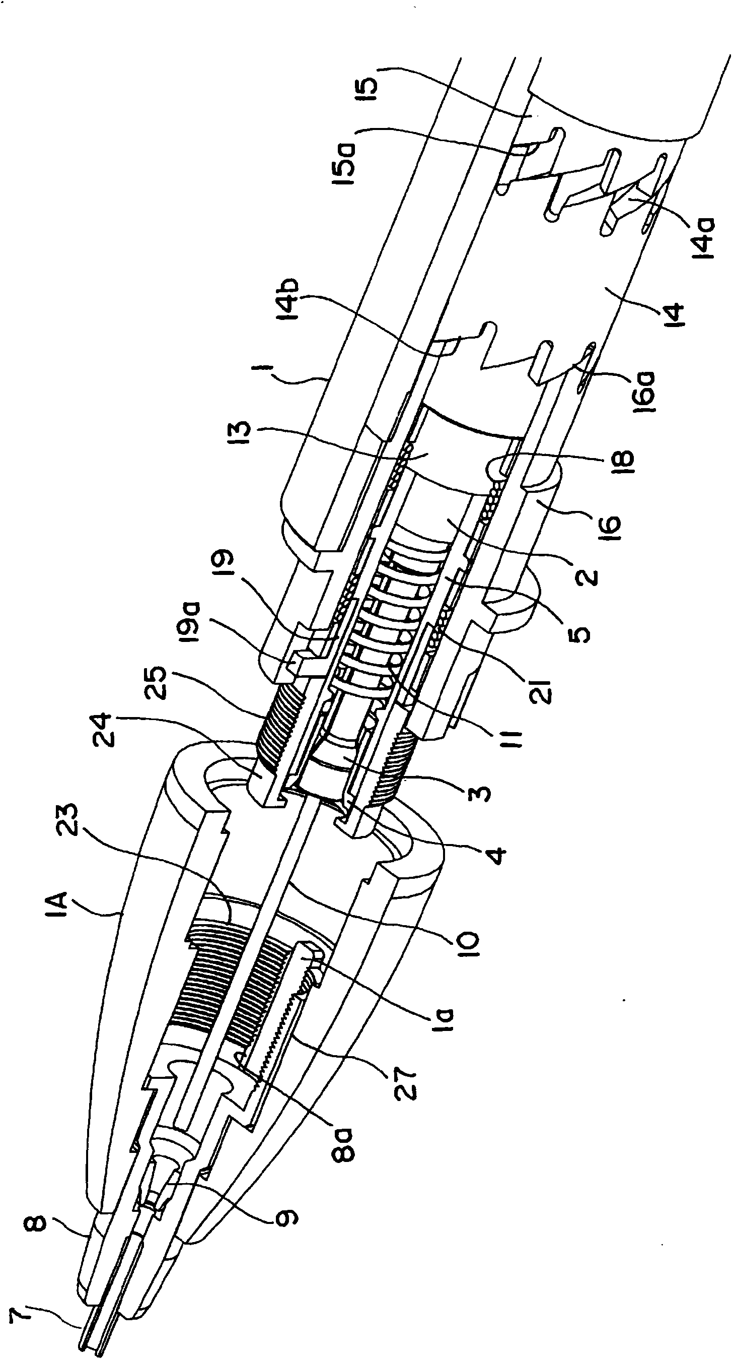
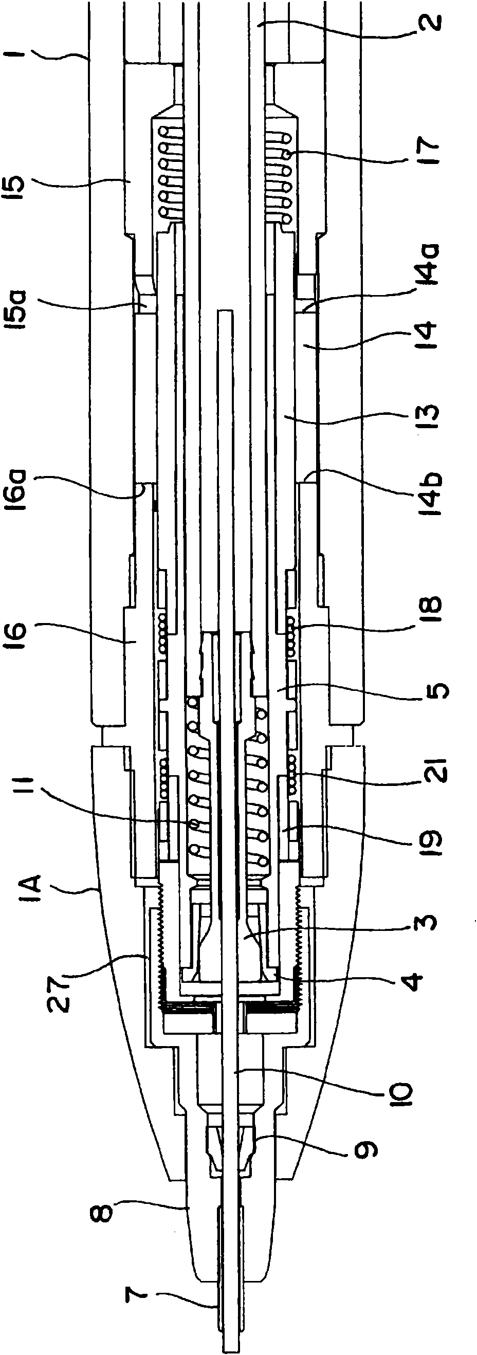
[0068] Hereinafter, the mechanical pencil of the present invention will be described based on the illustrated embodiment. Figure 1 ~ Figure 3 Shows the first embodiment of the mechanical pencil of the present invention, figure 1 It shows the front half of the mechanical pencil, and shows a perspective view in a state where the tip of the mouth is separated from the shaft barrel and a part is cut away. In addition, figure 2 Is a cross-sectional view of the front half showing a state cut along its axial direction, image 3 For being with figure 2 The state shown is a cross-sectional view of a state cut through a plane orthogonal to 90 degrees.

[0069] In addition, in the following, the structure of each part denoting the same part with the same symbol is described separately by the reference symbol, but in each figure described below, a part of the symbol is appropriately omitted according to the figure.

[0070] The symbol 1 denotes a shaft barrel constituting its outline. The s...


PUM


Abstract

This aims to provide a pipe-slide type mechanical pencil capable of confining the protrusion of a writing lead from a tip pipe, within a predetermined range. The mechanical pencil comprises a rotary drive mechanism constituted to let off a writing lead (10) forward by the forward and backward movements of a chuck (3) arranged in a cylinder (1) thereby to release and grip the writing lead, and to turn a rotor (5) in one direction in response to both the backward motion by a writing pressure received by the writing lead and the forward motion by the release of the writing pressure. Further comprised are a pipe supporting member (8) accommodated in a tip unit (1A) forming the tip of the cylinder, for supporting a tip pipe (7), and a backward drive mechanism for moving back the tip pipe supported by the pipe supporting member, gradually toward the cylinder in response to the rotary drive action of the rotor constituting the rotary drive mechanism.

Description

Technical field [0001] The present invention relates to a mechanical pencil, which is capable of protruding the pen core from the tip of the mouth by a pressing operation, and can retract a tubular core guide arranged at the tip of the mouth according to the wear of the pen core as writing mechanical pencil. Background technique [0002] A tubular core guide is fixedly attached to the tip of the mouth of a conventional mechanical pencil. According to this structure, when the protruding amount of the pen core protruding from the core guide is large, the core will be broken (core breakage) due to writing, so it is necessary to check the length of the core protruding from the core guide by one pressing operation Be restricted. [0003] Therefore, according to the consumption of the core accompanying the writing operation, the pressing lever provided at the rear end of the core barrel has to be frequently pressed. In other words, since it is necessary to change the pen holding actio...

Claims


Application Information

Patent Timeline
Patent Type & Authority Applications(China)
IPC IPC(8): B43K21/00B43K21/027B43K21/16
CPCB43K21/003B43K21/16B43K21/22
Inventor 大泽典生福本刚生小佐野芳寿小林武井泽弘壮中山协
Owner MITSUBISHI PENCIL CO LTD
Why Eureka
Eureka Blog
Learn More