
High-efficiency short-stroke linear reciprocating oscillation motor

A technology of linear reciprocating and oscillating motors, applied to electrical components, electromechanical devices, etc., can solve problems such as low system efficiency, achieve broad application prospects, low temperature rise, and improve efficiency and life.

Active Publication Date: 2012-05-30
HARBIN INST OF TECH
View PDF0 Cites 0 Cited by
  • Summary
  • Abstract
  • Description
  • Claims
  • Application Information

AI Technical Summary

Problems solved by technology

[0004] The purpose of the present invention is to solve the problem that the existing short-stroke linear reciprocating oscillating motor adopts a support leaf spring as the motor mover support and elastic restoring force generating device, and the system efficiency is low, and to provide a high-efficiency short-stroke linear reciprocating oscillating motor

Method used


Image

  • High-efficiency short-stroke linear reciprocating oscillation motor
  • High-efficiency short-stroke linear reciprocating oscillation motor
  • High-efficiency short-stroke linear reciprocating oscillation motor

Examples


specific Embodiment approach 1

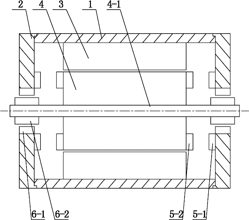
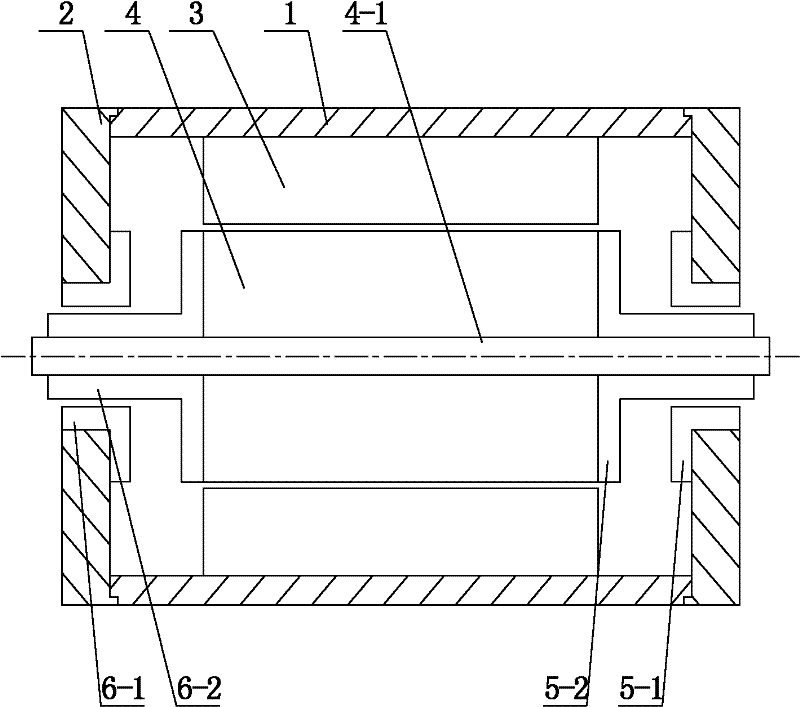
[0032] Specific implementation mode one: the following combination figure 1 and figure 2 Describe this embodiment, the high-efficiency short-stroke linear reciprocating oscillating motor described in this embodiment includes a cylindrical motor housing 1, two end covers 2, a motor stator 3 and a motor mover 4, and the cylindrical motor The two ends of the machine housing 1 are respectively fixedly connected with an end cover 2, and the center of the end cover 2 is provided with a central through hole, and the outer wall surface of the motor stator 3 is centered and fixed on the inner wall surface of the cylindrical motor housing 1. The rotor 4 is located in the inner cavity of the motor stator 3, and is arranged coaxially with the motor stator 3 and the cylindrical motor housing 1. through the center via hole,

[0033] It also includes two magnetic accumulators and two linear magnetic bearings,

[0034] The magnetic accumulator is composed of an accumulator stator 5-1 and...

specific Embodiment approach 2

[0043] Specific implementation mode two: the following combination figure 2 Describe this embodiment. This embodiment is a further description of Embodiment 1. The accumulator stator 5-1 and the bearing stator 6-1 have an integrated structure, and the accumulator mover 5-2 and the bearing mover 6 -2 One-piece structure. Other components and connections are the same as those in Embodiment 1.

specific Embodiment approach 3

[0044] Specific Embodiment 3: This embodiment is a further description of Embodiment 1 or 2. The bearing stator 6-1 and bearing mover 6-2 of the linear magnetic bearing adopt radial magnetization, and the bearing stator 6-1 and The bearing movers 6-2 are all assembled by a plurality of permanent magnets along the circumferential direction. Other compositions and connections are the same as those in the first or second embodiment.

[0045] In this embodiment, the bearing stator 6-1 and the bearing mover 6-2 are radially magnetized in segments.


PUM


Abstract

The invention relates to a high-efficiency short-stroke linear reciprocating oscillation motor, belonging to the technical field of motors. The invention solves the problem that the traditional short-stroke linear reciprocating oscillation motor using a support leaf spring as a motor rotor support and elasticity restoring force generator has low system efficiency. The high-efficiency short-strokelinear reciprocating oscillation motor comprises a motor shell, two end covers, a motor stator, a motor rotor, two magnetic power accumulators and two linear magnetic bearings. Two power accumulator stators are respectively located on the axial inner side surface at the through-hole end in the centre of two end covers; two power accumulator rotors are respectively fixed on two axial end surfaces of the motor rotor; both the power accumulator stator and the power accumulator rotor are annular rare earth permanent magnets or axial symmetry type rare earth permanent magnets; both the bearing stator and the bearing rotor are cylindrical rare earth permanent magnets; two bearing stators are respectively sleeved and fixed on the inner surfaces of the central through holes of two end covers; twobearing rotors are respectively sleeved at both ends of an output shaft of the motor rotor; and the bearing stator is arranged opposite to the bearing rotor. The invention is suitable for a linear reciprocating oscillation motor.

Description

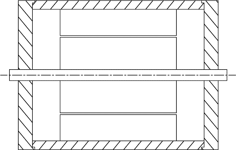
technical field [0001] The invention relates to a high-efficiency short-stroke linear reciprocating oscillating motor, which belongs to the technical field of motors. Background technique [0002] A common structure of a short-stroke linear reciprocating oscillating motor is as follows: image 3 shown. It is mainly composed of motor stator, motor mover and supporting leaf spring. The specific structure of supporting leaf spring is as follows: Figure 4 As shown, it is fixed on both sides of the motor stator in the axial direction and connected to the output shaft of the mover. On the one hand, the supporting leaf spring keeps the motor mover in the inner cavity of the motor stator to prevent the motor mover from radially contacting the motor. The inner cavity of the stator is in contact. On the other hand, the supporting leaf spring will also generate an axial restoring force, so that the spring-mass system composed of the motor mover and the supporting leaf spring will res...

Claims


Application Information

Patent Timeline
Patent Type & Authority Patents(China)
IPC IPC(8): H02K33/18
Inventor 寇宝泉张海林周维正
Owner HARBIN INST OF TECH
Learn More