
Fire extinguishing system of wind generating set

A technology of wind power generators and fire extinguishing systems, applied in the field of fire extinguishing systems, can solve problems affecting precision instruments and equipment, high system cost, and unusable places with people, so as to achieve the effects of improving safety, good fire extinguishing effect, and reducing damage

Inactive Publication Date: 2012-01-11
CRRC WIND POWER(SHANDONG) CO LTD
View PDF0 Cites 0 Cited by
  • Summary
  • Abstract
  • Description
  • Claims
  • Application Information

AI Technical Summary

Problems solved by technology

[0004] Among the above types of gas fire extinguishing systems, which one is more suitable for protecting electrical equipment fires in the wind turbine nacelle, let's compare their advantages and disadvantages first: (1) Carbon dioxide cannot be used in places where people During the release process, a large amount of dry ice will be generated, which will cause the temperature in the protection area to drop sharply, which will affect precision instruments and equipment. At the same time, dry ice will also block the nozzle and cause accidents.
(2) After hot aerosol prefabricated fire extinguishing, the residue is a non-clean fire extinguishing agent, and the product after spraying will cause damage to electrical and electronic equipment, so it is not suitable for protecting sites that occupy a lot of equipment
(3) The inert gas fire extinguishing storage pressure of IG541 fire extinguishing agent is 15Mpa ~ 20Mpa, which belongs to the high pressure system, and its system cost is the most expensive among all fire fighting equipment

Method used


Image

  • Fire extinguishing system of wind generating set
  • Fire extinguishing system of wind generating set
  • Fire extinguishing system of wind generating set

Examples


Embodiment Construction

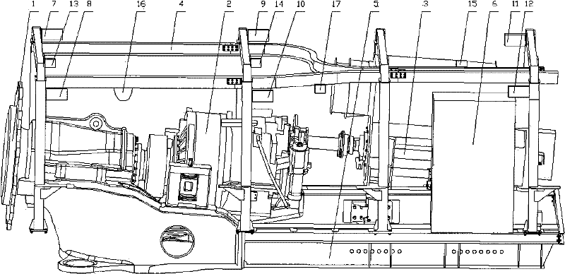
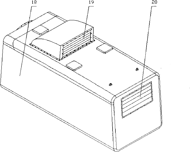
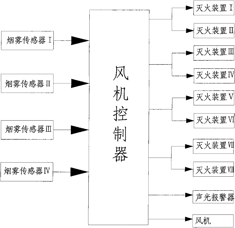
[0020] like figure 1 , 2 , 3, 4, the accompanying drawing provides an example of the present invention, the present invention will be further described below in conjunction with accompanying drawing and example, but protection of the present invention is not limited to the content shown in example. In the present invention, a main shaft 1 , a gear box 2 , a generator 3 , an internal frame 4 , a nacelle underframe 5 and a fan controller 6 are arranged in the nacelle. The nacelle outer cover is a nacelle cover 18 on which electric control shutters are installed, six fire extinguishers and three smoke sensors are all distributed in the wind turbine nacelle, and the sound and light alarm 16 is also installed in the wind turbine nacelle. The signal input end of the fan controller 6 is connected with the signal output ends of the smoke sensor and the pressure sensor 17, and the control signal output end of the fan controller 6 is connected with the control signal input ends of the ...


PUM


Abstract

The invention discloses a fire extinguishing system of a wind generating set, belonging to the technical field of wind power generation. The fire extinguishing system of the wind generating set is connected with a fan controller; the signal input end of the fan controller is connected with the signal output end of a smoke sensor used for detecting smoke inside a machinery space and the signal output end of a pressure sensor used for detecting pressure inside the machinery space; the control signal output end of the fan controller is connected with a fan, a fire extinguishing device and the control signal input end of an electric control shutter used for forming a closed space in the machinery space after being closed; and the fan controller analyzes and processes signals of the smoke sensor and the pressure sensor and then sends control signals of shutting down the fan, starting or shutting down the fire extinguishing device and opening or closing the electric control shutter. The invention has the advantages that the fan can be fast shut down and the fire extinguishing device is started to fast carry out fire extinguishing processing on the machinery space, and the electric control shutter is automatically closed to ensure the concentration of a fire extinguishing agent inside the machinery space, thereby having good fire extinguishing effect.

Description

technical field [0001] The invention belongs to the technical field of wind power generation, in particular to a fire extinguishing system of a wind power generating set. Background technique [0002] At present, there are a large number of electrical equipment in the nacelle of the wind turbine, which is the main control part of the wind turbine. The fire inside the nacelle will cause serious damage to the wind turbine. With the rapid development of the wind power industry, the potential damage of the fire to the wind turbine will become more and more serious. However, common fire extinguishing devices often have the problems of untimely fire extinguishing, poor fire extinguishing effect, and easy damage to electrical components in common fire extinguishing devices. Therefore, it is particularly urgent to develop a suitable gas fire extinguishing device for wind turbines. [0003] The gas fire extinguishing device is used in places where water cannot be used to extinguish...

Claims


Application Information

Patent Timeline
Patent Type & Authority Patents(China)
IPC IPC(8): A62C3/16
Inventor 吴得宗郝君勇赵磊
Owner CRRC WIND POWER(SHANDONG) CO LTD
Learn More