Fiber strain sensitive structure and manufacturing method thereof

A technology of optical fiber strain and sensitive structure, applied in the direction of using optical devices, optical waveguide coupling, measurement devices, etc., can solve the problems of limited capillary structure, limited elastic range, easy fatigue, etc., to reduce manufacturing costs, flexibility Large range, performance-enhancing effect

Inactive Publication Date: 2011-02-02
SHANGHAI KNP CHEM +3
View PDF15 Cites 16 Cited by
  • Summary
  • Abstract
  • Description
  • Claims
  • Application Information

AI Technical Summary

Problems solved by technology

This structure is linear, but the elastic range is still limited by the capillary material
In addition, the Chinese invention patent with the publication number CN1316227C proposes a displacement sensor composed of a fiber grating capillary strain sensor connected in series with a spring. If the structure is used as a strain sensor, although the elastic range increases, it is still limited by the capillary structure. and the non-linear error caused by the series
The third structure, such as the U.S. patent with publication number US6047094, uses a composite material to wrap the optical fiber sensitive unit, and the elastic range is greatly improved, but the linearity is poor
This type of structure has improved in terms of elastic range and linearity, but has the problem of being prone to fatigue

Method used


Image

  • Fiber strain sensitive structure and manufacturing method thereof
  • Fiber strain sensitive structure and manufacturing method thereof
  • Fiber strain sensitive structure and manufacturing method thereof

Examples


Embodiment Construction

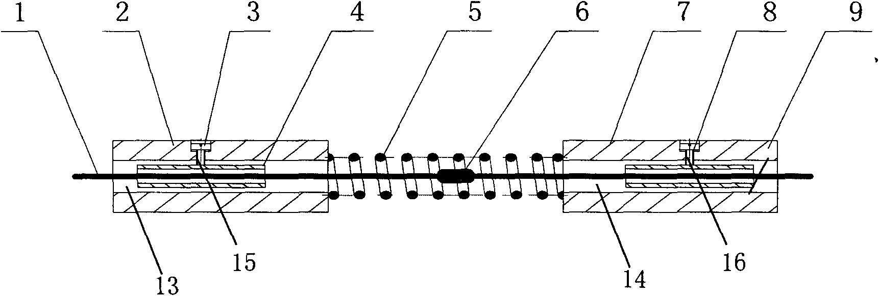
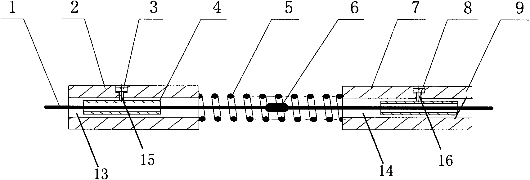
[0025] Such as figure 1 As shown, the optical fiber strain sensitive structure of the present invention includes: an optical fiber 1 provided with an optical fiber strain sensitive unit 6, a left optical fiber holder 2, a spring 5 and a right optical fiber holder 7 arranged in sequence and fixedly connected to each other, and a left optical fiber holder 2 A first through hole 13 communicating with the left and right is provided, and a second through hole 14 communicating with the left and right is provided in the right optical fiber fixing base 7 . The optical fiber 1 is glued together with the left fiber fixing capillary 4 and the right fiber fixing capillary 9 which are sleeved on the fiber 1 and located on the left and right sides of the fiber strain sensitive unit 6 respectively to form an optical fiber assembly. The fiber assembly passes through the first through hole 13, the spring 5 and the second through hole 14, so that the left fiber fixing capillary 4 is placed and ...


PUM


Abstract

The invention discloses a fiber strain sensitive structure and a manufacturing method thereof. The fiber strain sensitive structure comprises a left fiber fixing seat, a spring and a right fiber fixed seat which are in fixed connection in sequence, wherein the left fiber fixed seat is provided with a first through hole of which the left and right ends are communicated; the right fiber fixed seat is provided with a second through hole of which the left and right ends are communicated; and after penetrating through the first through hole of the left fiber fixed seat, the spring and the second through hole of the right fiber fixed seat, the fiber is stretched and fixed to the left and right fiber fixed seats; and a fiber strain sensitive unit on the fiber is positioned in the spring. The fiber strain sensitive structure has the characteristics of bidirectional stress strain, wide elastic range, favorable linearity, fatigue resistance, simple manufacturing method and low cost.

Description

technical field [0001] The invention relates to the field of optical fiber sensors, in particular to an optical fiber strain sensitive structure and a manufacturing method thereof. Background technique [0002] Optical fiber sensing technology is more and more widely used in various industrial and military fields due to its advantages of no electricity, intrinsic immunity from electromagnetic interference, long-distance detection and resistance to harsh environments. With the development of optical fiber sensing technology, various optical fiber strain sensors that play an important role in this technical field continue to appear, but their strain-sensitive structures mainly include the following types: [0003] One) sheet structure, such as metal sheet, film, composite sheet, etc., the patents with publication numbers CN2550719Y, CN2706738Y, and CN2627460Y disclose this structure. This kind of structure is simple and easy to implement, but the elastic range is small, the l...

Claims


Application Information

Patent Timeline
IPC IPC(8): G01B11/16G02B6/36
Inventor 钱洪卫陆宗源张杰何唯平
Owner SHANGHAI KNP CHEM
Why Eureka
Try Eureka