Eureka AIR delivers breakthrough ideas for toughest innovation challenges, trusted by R&D personnel around the world.

High total pressure large-flow wheel disk side beveling type back-ward impeller fan

A backward-curved impeller, high-flow technology, applied in mechanical equipment, machines/engines, liquid fuel engines, etc., can solve the problems of centrifugal fan radial exhaust that does not meet the requirements, low operating efficiency, and large fan volume. The effect of increasing the effective work area, reducing the loss and increasing the degree of expansion

Active Publication Date: 2011-02-02
DALIAN UNIV OF TECH
View PDF4 Cites 10 Cited by
  • Summary
  • Abstract
  • Description
  • Claims
  • Application Information

AI Technical Summary

Problems solved by technology

Although the general axial flow fan meets the requirements of axial exhaust, its pressure head is low and it is difficult to meet the requirements; while the centrifugal fan has the characteristics of high total pressure coefficient and large flow coefficient, but the centrifugal fan has the characteristics of high flow rate operating point. The operating efficiency is low, the volume of the fan is large, and the radial exhaust of the centrifugal fan does not meet the requirements. All these require a new design and innovation of the centrifugal fan to further improve its performance, reduce its energy consumption, and meet the cooling requirements of the EMU.

Method used


Image

  • High total pressure large-flow wheel disk side beveling type back-ward impeller fan
  • High total pressure large-flow wheel disk side beveling type back-ward impeller fan
  • High total pressure large-flow wheel disk side beveling type back-ward impeller fan

Examples


Embodiment Construction

[0025] The present invention is further described in conjunction with the above technical solutions and accompanying drawings.

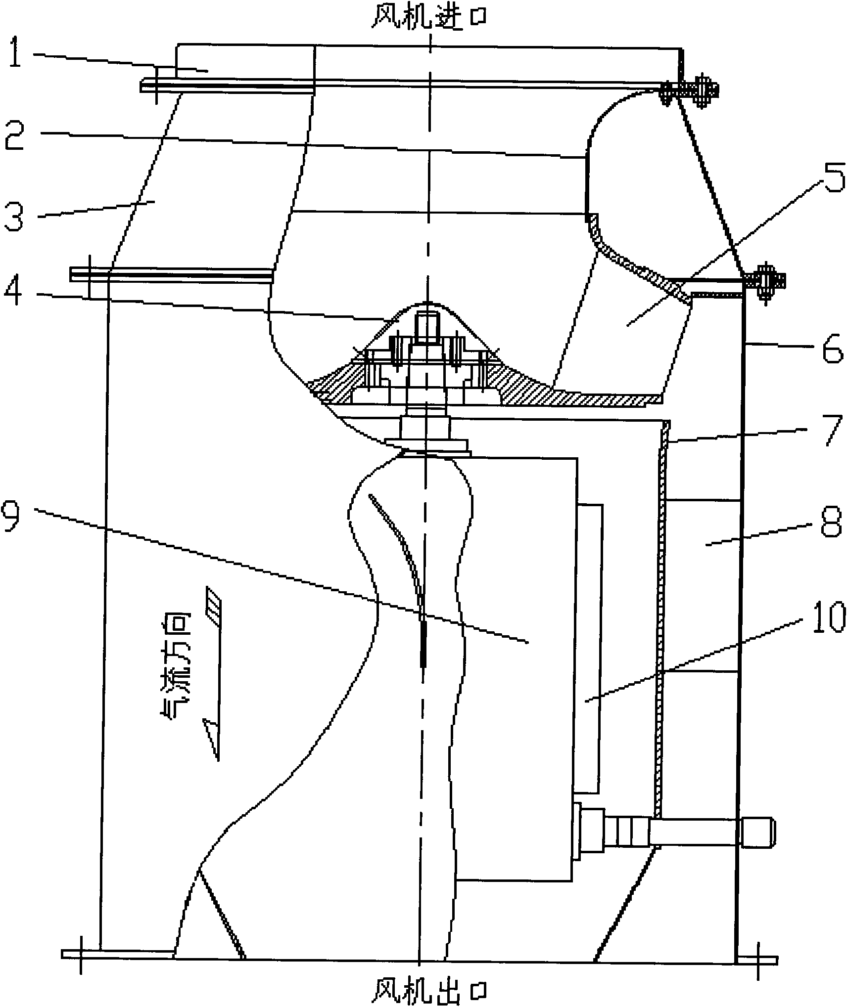
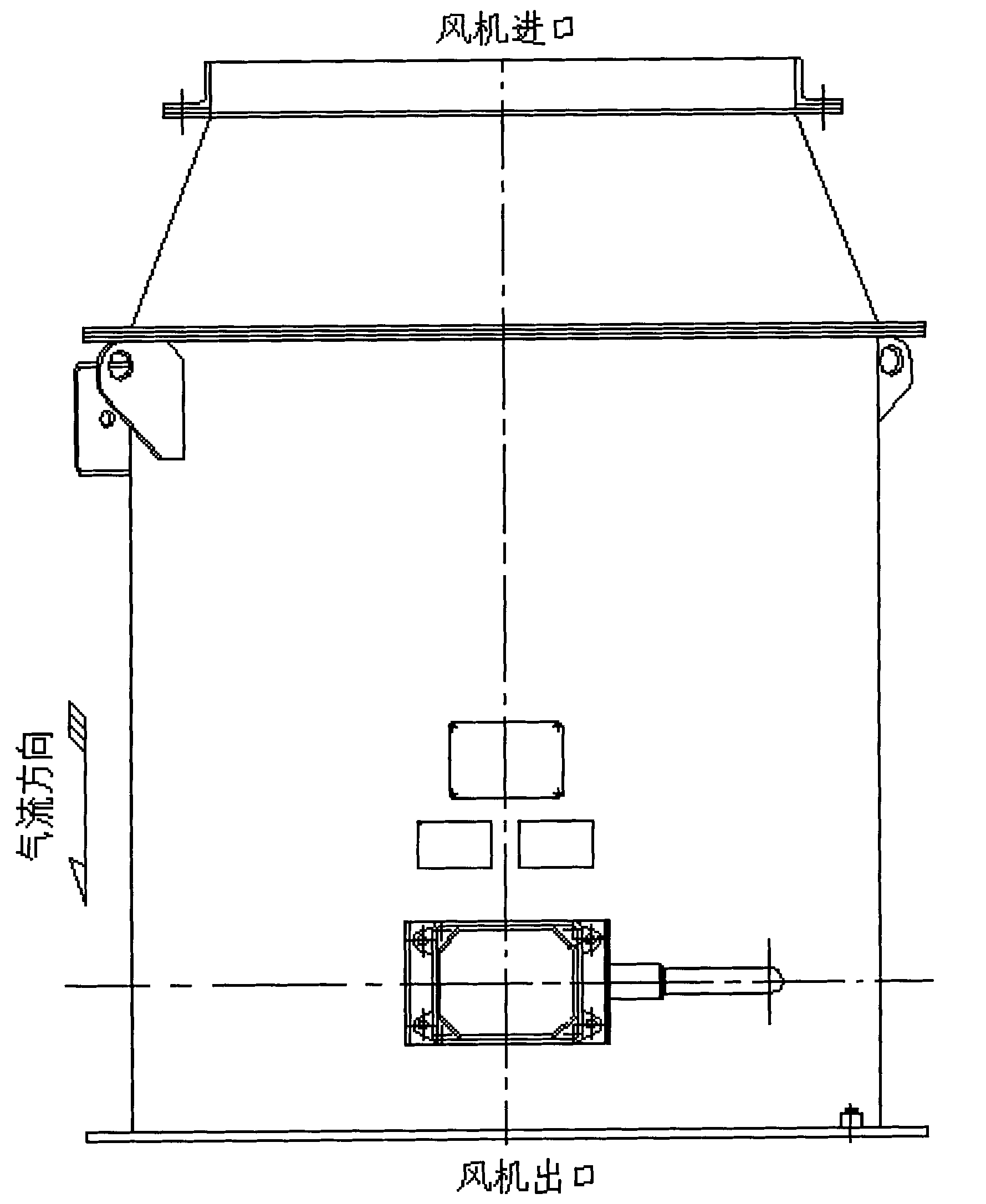
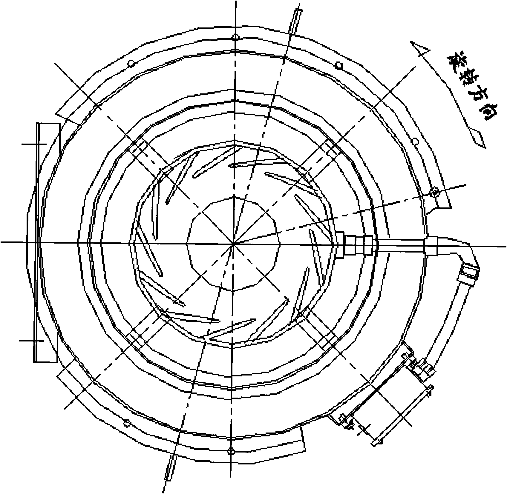
[0026] As shown in the figure, a high full-pressure and large-flow disc-side beveled backward-curved impeller fan according to the present invention consists of an angle steel flange 1, an air guide cover 2, an air inlet tube 3, an inlet guide cover 4, The impeller 5, the outer cylinder of the air outlet cylinder 6, the inner cylinder of the air outlet cylinder 7, the guide vane 8, the motor 9 and the bracket 10 etc. are composed. The impeller 5 is placed in the air inlet tube 3 and connected with the motor 9, and the motor 9 is fixed on the inner cylinder 7 of the air outlet tube through a bracket 10. The end of the air inlet tube is provided with an air inlet, and the air outlet tube includes two parts: the outer cylinder of the air outlet tube 6 and the inner tube of the air outlet tube 7. The cylinder inner cylinder 6 and the motor 9 constitute ...


PUM


Abstract

The invention discloses a high total pressure large-flow wheel disk side beveling type back-ward impeller fan, belonging to the technical field of fans. The fan is characterized by being composed of an angle iron flange, a wind scooper, an air intake barrel, a rotor cap, an impeller, the outer barrel of an air outlet barrel, the inner barrel of the air outlet barrel, a guide vane, a motor, a bracket and the like, wherein the inlet of the fan is provided with the wind scooper and extends into the inlet part of the impeller; the hub of the impeller is additionally provided with the rotor cap; the outlet of the impeller, i.e. the edge of the wheel disk, adopts a bevelling structure, and the impeller vane has two types of linear type and circular arc type; the joint assembly point of the air intake barrel and the air outlet barrel of the impeller, i.e. the wheel cover side of the impeller outlet, is provided with the baffle; the isopachous guide vane is welded between the inner barrel of the air outlet barrel and the outer barrel of the air outlet barrel; the side of the inner barrel and outer barrel of the air outlet barrel, which is near the wheel disk of the impeller, is opened; and the air outlet of the fan is divided into a main runner air outlet and a motor cooling flow air outlet. The invention not only satisfies the requirements of high total pressure and large flow operation of the cooling fan but also improves the air flowing situation in the fan to lower flowing loss and noise.

Description

technical field [0001] The invention belongs to the technical field of ventilators, and relates to a high-full-pressure, high-flow, disc-side oblique-cut type backward-curved impeller ventilator, which is applied to high-pressure, high-flow cooling and ventilation of locomotive traction motors and related equipment. Background technique [0002] The traction motor of the EMU locomotive has the characteristics of high power and many heating electrical components. With the increase of the train speed, the negative pressure on the train surface increases. At this time, the pressure head required by the original locomotive cooling fan increases, and the cooling flow will decrease. , when the situation is serious, the heating components of the EMU, such as electrical equipment, will be overheated and damaged, which requires the matching cooling fan to have the characteristics of large flow and high total pressure; The space occupied by the fan restricts the working capacity of th...

Claims


Application Information

Patent Timeline
Patent Type & Authority Applications(China)
IPC IPC(8): F04D29/58F04D29/32F04D29/54F04D25/08
Inventor 王晓放崔利斌于洋田夫姜治迅吴联军隋锡征赵广
Owner DALIAN UNIV OF TECH
Why Eureka
Eureka Blog
Learn More