Eureka AIR delivers breakthrough ideas for toughest innovation challenges, trusted by R&D personnel around the world.

Turbine disc and gas turbine

A turbine disk and cooling hole technology, which is applied to the cooling of turbine/propulsion devices, mechanical equipment, engine functions, etc., can solve the problems of thicker thickness, high cost, and insufficient durability of turbine disks, etc., to alleviate stress concentration , realize the effect of reducing weight and improving cooling efficiency

Active Publication Date: 2013-09-11
MITSUBISHI POWER LTD
View PDF1 Cites 0 Cited by
  • Summary
  • Abstract
  • Description
  • Claims
  • Application Information

AI Technical Summary

Problems solved by technology

As a result, the durability of the turbine disk becomes insufficient, and countermeasures such as using a high-strength material or increasing the thickness are necessary, and there is a problem of causing high cost.

Method used


Image

  • Turbine disc and gas turbine
  • Turbine disc and gas turbine
  • Turbine disc and gas turbine

Examples


Embodiment

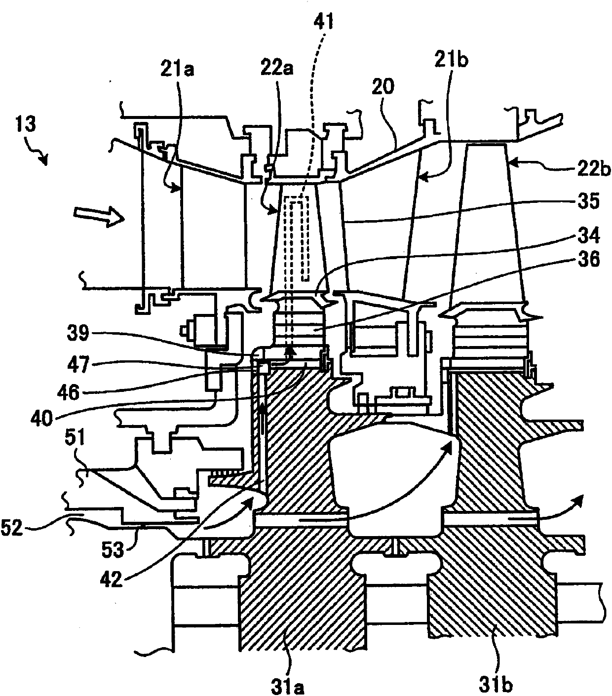
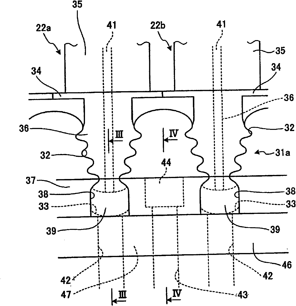
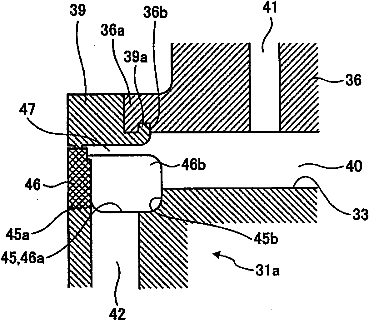
[0051] figure 1 It is a schematic diagram of a turbine upstream part in a gas turbine according to an embodiment of the present invention. figure 2 It is a front view of main parts of the turbine disk of the gas turbine according to the present embodiment. image 3 yes figure 2 Sectional view of III-III. Figure 4 yes figure 2 Sectional view of IV-IV. Figure 5 It is an exploded perspective view of the rotor blade of the gas turbine of this embodiment. Figure 6 It is an explanatory diagram showing the relationship among the diameter, interval, and stress concentration factor of cooling holes. Figure 7 It is a graph showing the stress concentration factor with respect to the diameter and spacing of cooling holes. Figure 8 is a schematic configuration diagram of the gas turbine of this embodiment. Figure 9 is a schematic diagram showing a modified example of the turbine disk of the gas turbine of the present embodiment.

[0052] The gas turbine of this embodiment, s...


PUM


Abstract

In a turbine disk and a gas turbine, the turbine disk is firmly connected to a rotor (24) to be rotatably supported; a plurality of rotor blades (22a) is arranged on an outer circumference thereof in a circumferential direction; first cooling holes (42) penetrating the turbine disk from inside toward outside thereof and being communicatively connected to a cooling passage (41) arranged inside of the rotor blades (22a) are arranged in the circumferential direction; second cooling holes (43) arranged between each of the first cooling holes (42) and penetrating the turbine disk from the inside toward the outside thereof are provided; and the first cooling holes (42) and the second cooling holes (43) are communicatively connected by way of a radial direction communicating channel (47), to alleviate concentration of stress and to improve durability.

Description

technical field [0001] The present invention relates to a turbine disk which is rotatably mounted, for example, in a gas turbine that combusts compressed high-temperature, high-pressure air supplied with fuel and supplies the resulting combustion gas to a turbine to obtain rotational power, and a gas turbine having the turbine disk. A plurality of rotor blades are supported and provided on the outer periphery. Background technique [0002] A gas turbine consists of a compressor, a combustor, and a turbine. The air taken in from the air inlet is compressed by the compressor to become high-temperature and high-pressure compressed air. The fuel supplied with the compressed air is combusted by the combustor. The high-temperature, high-pressure combustion gas drives a turbine, which drives an electric generator connected to the turbine. The turbine is composed of a plurality of stationary blades and moving blades arranged alternately in the engine room, and the output shaft co...

Claims


Application Information

Patent Timeline
Patent Type & Authority Patents(China)
IPC IPC(8): F01D5/08F01D5/00F01D5/02F02C7/18
CPCF01D5/087F05D2260/941F01D5/081F01D5/323
Inventor 桥本真也荒濑谦一
Owner MITSUBISHI POWER LTD
Why Eureka
Eureka Blog
Learn More