Supercharge Your Innovation With Domain-Expert AI Agents!

Electro-optical apparatus, electronic appliance and method of driving electro-optical apparatus

A technology of electro-optical devices and driving methods, which can be applied to circuits, electrical components, electric solid-state devices, etc., and can solve problems such as the inability to establish driving methods

Inactive Publication Date: 2011-01-26
SEIKO EPSON CORP
View PDF8 Cites 0 Cited by
  • Summary
  • Abstract
  • Description
  • Claims
  • Application Information

AI Technical Summary

Problems solved by technology

[0007] However, in the above-mentioned conventional technique of forming the gate insulating film of a thin film transistor from a ferroelectric material and making it into a variable polarization state, the driving method when it is applied to an electro-optical device including an electrophoretic device cannot be established.
As a result, there is a problem that it takes time for the display of the electro-optical device to change

Method used


Image

  • Electro-optical apparatus, electronic appliance and method of driving electro-optical apparatus
  • Electro-optical apparatus, electronic appliance and method of driving electro-optical apparatus
  • Electro-optical apparatus, electronic appliance and method of driving electro-optical apparatus

Examples


Embodiment 1

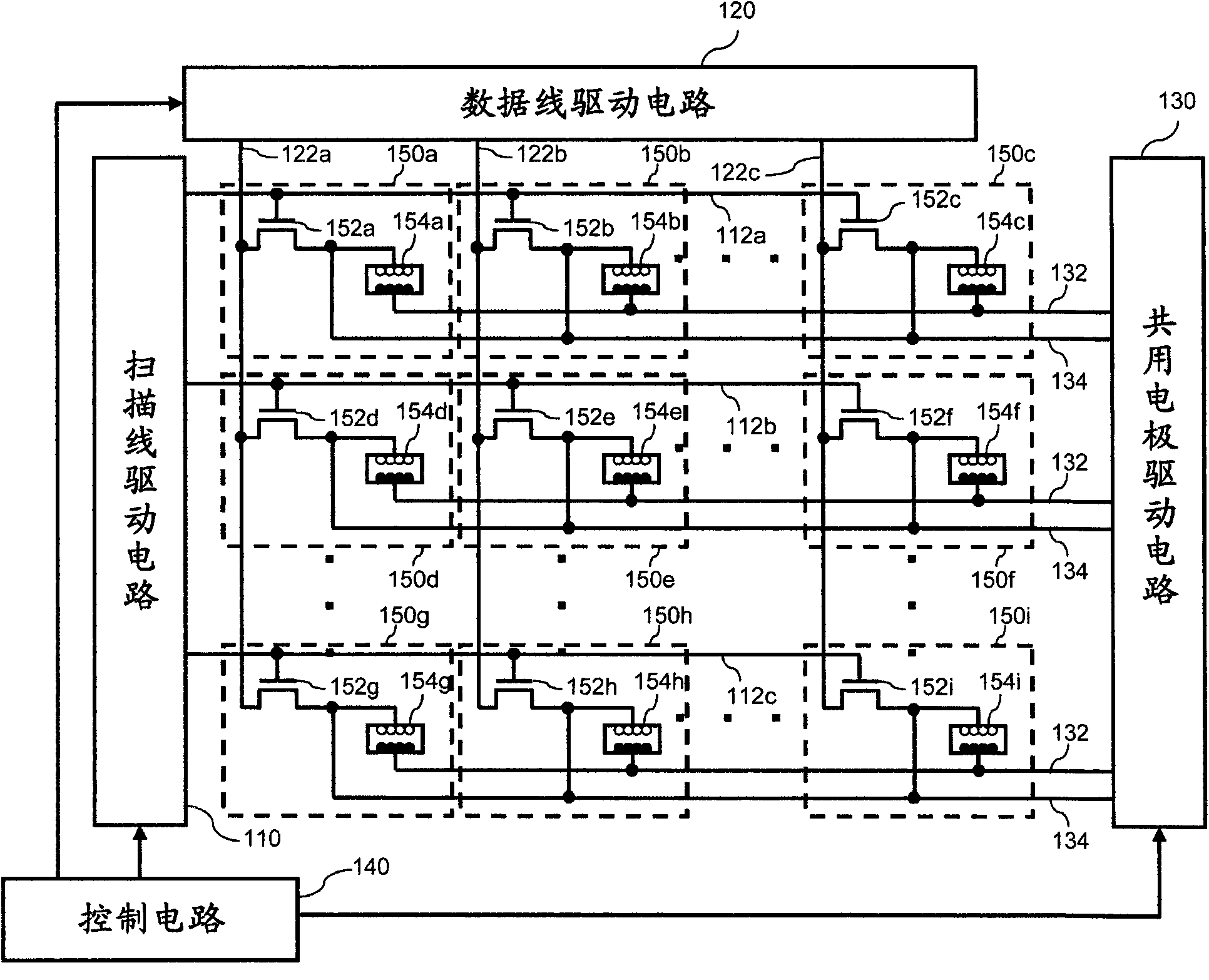
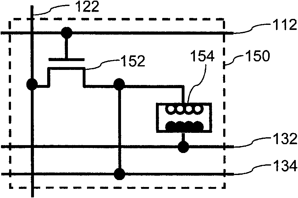
[0049] 2-1. Configuration example of electro-optic device

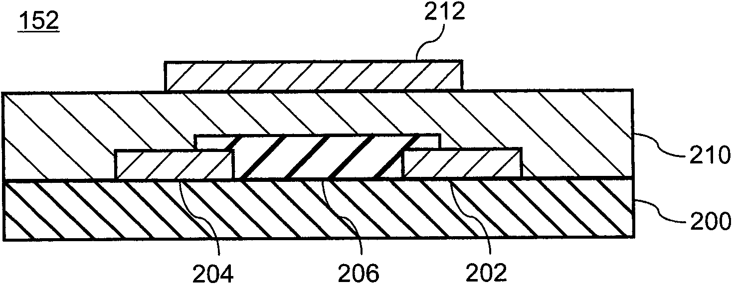
[0050] 2-2. Configuration examples and characteristics of transistors included in electro-optical devices

[0051] 2-3. Operation example of electro-optical device

[0052] (1) Changes in the polarization state of the transistor

[0053] (2) Display state changes

[0054] (3) Reset of display status

[0055] (4) Resetting of the polarization state of the transistor

Embodiment 2

[0057] 4. Examples of electronic equipment including electro-optical devices

[0058] 5. supplement

[0059]

[0060] First, the terms used in this specification are defined as follows.

[0061] "Pixel particles": Refers to the charged particles for display interposed between the common electrode and the pixel electrode in the pixel. Electrophoretic particles or particles of electronic powder fluid are exemplified as pixel particles, but are not limited thereto.


PUM


Abstract

The present invention provides an electro-optical apparatus and a method of driving an electro-optical apparatus with which it is possible to shorten the time required to change the display of an electro-optical apparatus. The apparatus includes a transistor exhibiting hysteresis, a pixel electrode and a common electrode opposing the pixel electrode, and a driving circuit. The first transistor's on / off state is selected according to a voltage between the scanning line and the data line. The on state is maintained even when application of the voltage ceases. The driving circuit, after sequentially selecting on state of all transistors, simultaneously changes the display states.

Description

technical field [0001] The present invention relates to an electro-optic device, an electronic device and a driving method of the electro-optic device. Background technique [0002] An electrophoretic device is a device that changes the voltage applied between electrodes sandwiching charged electrophoretic particles to move the electrophoretic particles, thereby changing the color tone in appearance and displaying images. An electro-optical device representing such an electrophoretic device changes the on / off of the thin film transistor by changing the voltage applied to the thin film transistor from the scanning line and the data line when changing the voltage applied between the electrodes. [0003] Conventionally, there has been a technique of forming the gate insulating layer of the thin film transistor from a ferroelectric material so that the polarization state can be changed. For example, Japanese Patent Laid-Open No. 61-260596 (Patent Document 1) discloses a technol...

Claims


Application Information

Patent Timeline
Patent Type & Authority Applications(China)
IPC IPC(8): G09G3/20G09G3/34H01L27/30
CPCG09G2300/08G09G3/344
Inventor 宫本勉
Owner SEIKO EPSON CORP
Features
  • R&D
  • Intellectual Property
  • Life Sciences
  • Materials
  • Tech Scout
  • Unparalleled Data Quality
  • Higher Quality Content
  • 60% Fewer Hallucinations
Learn More