Supercharge Your Innovation With Domain-Expert AI Agents!

Wavelength tuning device and wavelength tuning method

一种波长调节、波长的技术,应用在光波导的耦合、波分复用系统、电气元件等方向,能够解决波长变动、无法变更反射波长、传输品质恶化等问题,达到防止不期望的变动的效果

Inactive Publication Date: 2007-04-18
OKI ELECTRIC IND CO LTD
View PDF1 Cites 6 Cited by
  • Summary
  • Abstract
  • Description
  • Claims
  • Application Information

AI Technical Summary

Problems solved by technology

[0007] However, especially when FBG is used in the above-mentioned encoder / decoder, since the transmission quality deteriorates if the reflected wavelength of the FBG differs between the paired encoder and decoder, it is necessary to make the reflected wavelength substantially the same
The above method still produces wavelength fluctuations, and a wavelength difference between the encoder and decoder exceeds the level that does not deteriorate the transmission quality
Also, in the above method, the reflection wavelength determined when fixing the fiber cannot be changed
If the reflection wavelength of the FBG cannot be adjusted with respect to fluctuations in the wavelength of the light source, etc., there is a problem that the transmission quality deteriorates

Method used


Image

  • Wavelength tuning device and wavelength tuning method
  • Wavelength tuning device and wavelength tuning method
  • Wavelength tuning device and wavelength tuning method

Examples


no. 1 Embodiment approach

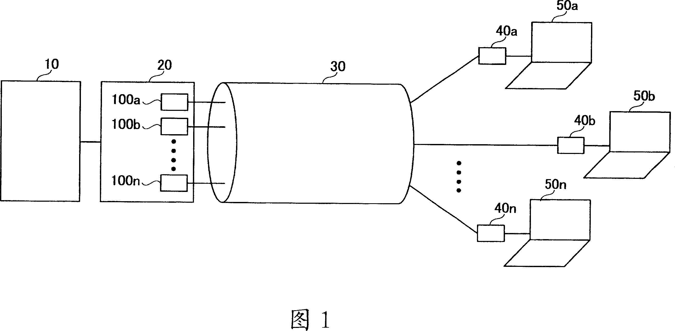
[0046] Next, an application of the wavelength adjuster of the present invention to the wavelength adjuster 100 that can be used as an encoder / decoder in phase code OCDM will be described. In an encoder / decoder of the phase encoding method OCDM, a superstructure FBG (Superstructure FBG, hereinafter also referred to as SSFBG) having a multipoint phase shift structure may be used. The SSFBG is a plurality of FBGs (hereinafter referred to as unit FBGs) having the same length and period of the refractive index change region (that is, the same reflection wavelength), and the interval between the unit FBGs that is arbitrarily set corresponding to the code to be formed is set. (also including 0). In this case, accurate decoding cannot be performed even if the wavelength difference between the paired encoder and decoder is only a few pm (picometer), so it is necessary to match the wavelengths of the encoder and decoder with high precision.

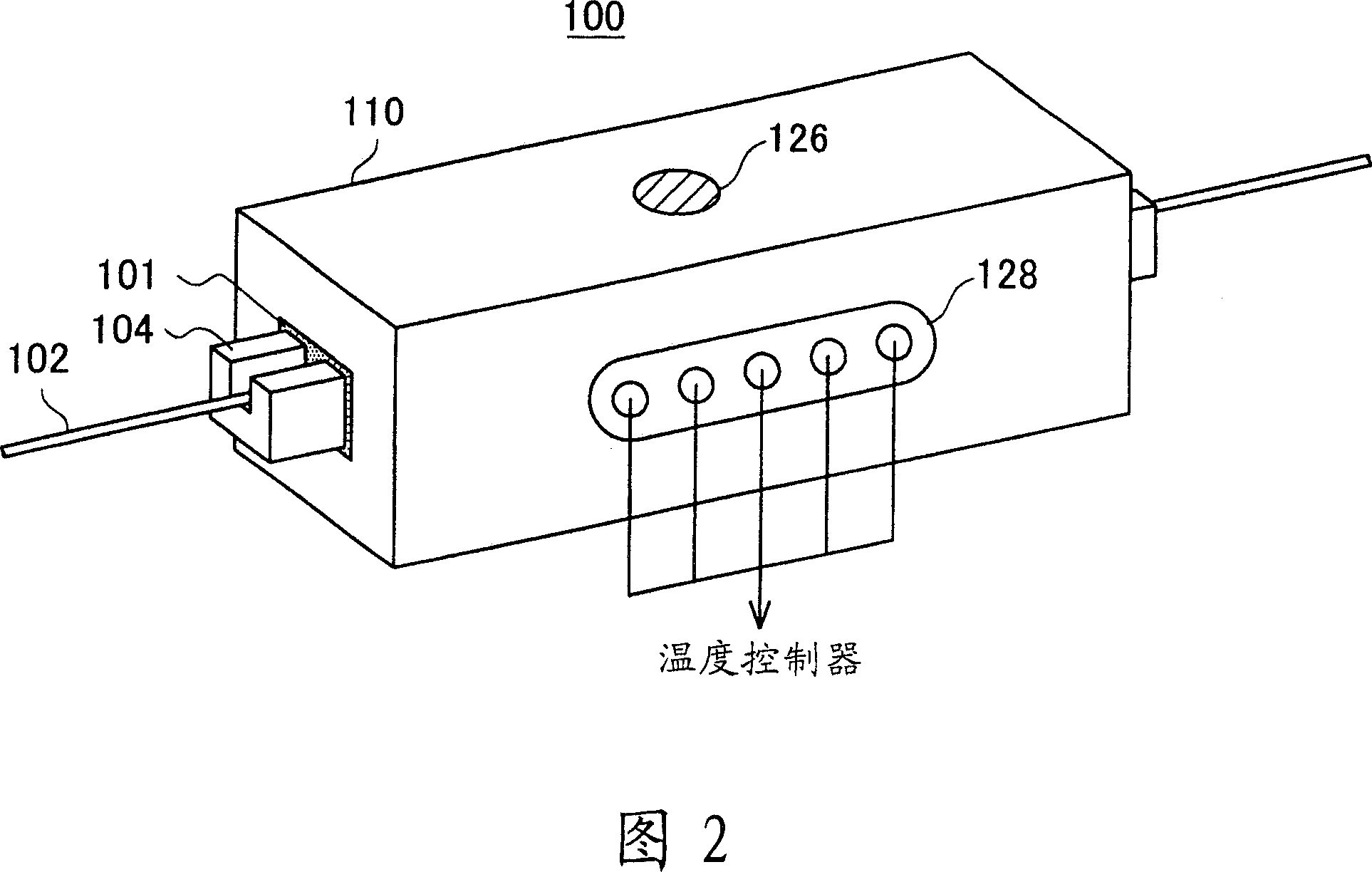
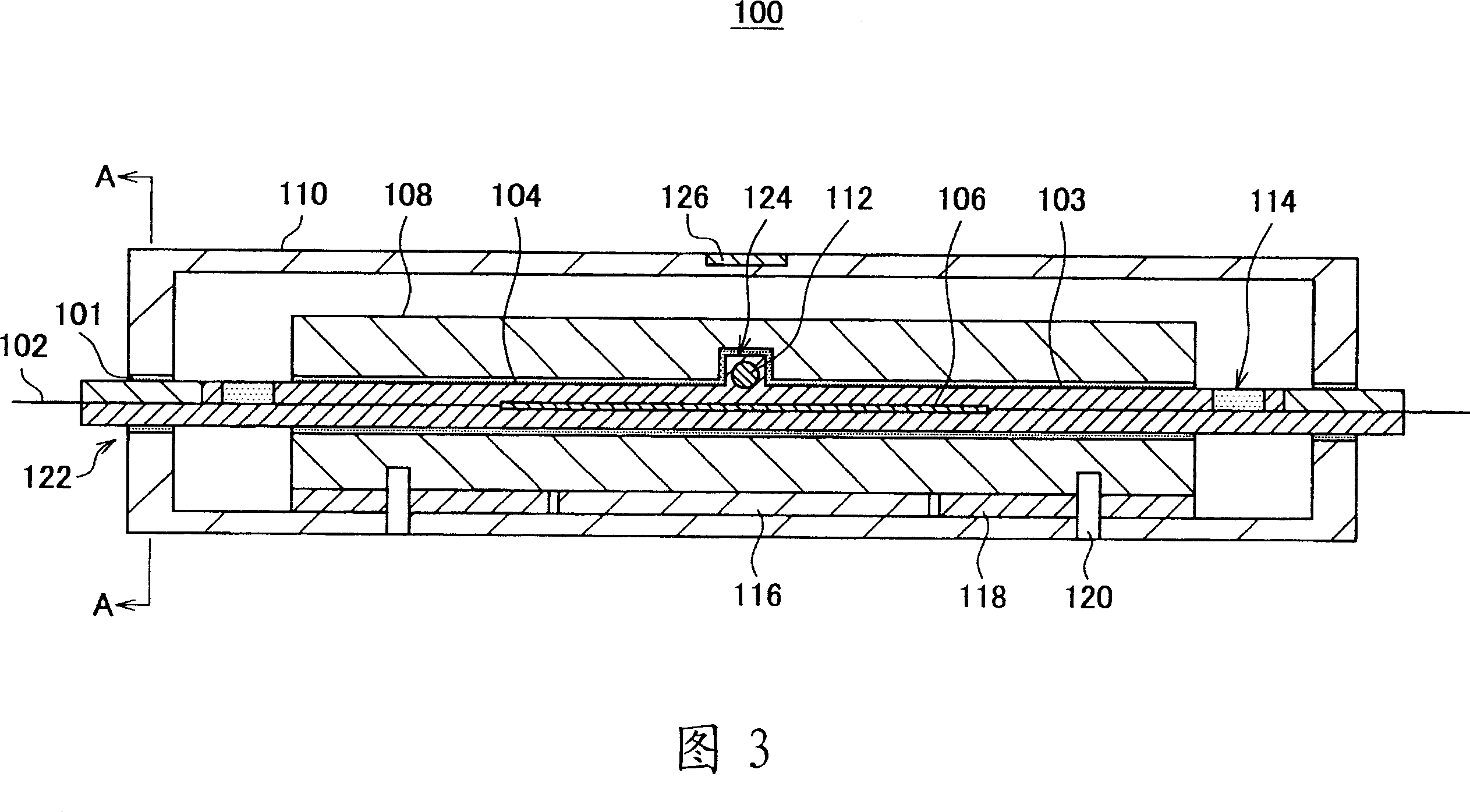
[0047] The wavelength adjuster 100 of this ...

no. 2 Embodiment approach

[0107] Next, a second embodiment of the present invention will be described. In the second embodiment, a wavelength adjuster 200 that can be used as an encoder / decoder in the phase encoding method OCDM will be described by applying the wavelength adjuster of the present invention. The wavelength adjuster 200 of the second embodiment has basically the same structure and function as the wavelength adjuster 100 of the first embodiment, but the base member is made of a bracket made of a material with high thermal conductivity and a bracket made of a material with low thermal conductivity. The difference from the wavelength adjuster 100 is that it is surrounded by a cover made of material. Hereinafter, constituent elements having basically the same structure and function as those of the wavelength adjuster 100 are given the same reference numerals in the drawings, and descriptions thereof are omitted, and portions different from those of the wavelength adjuster 100 will be describe...


PUM


Abstract

A wavelength tuning device of the invention tunes the reflected wavelength of a fiber Bragg grating, and includes: an optical fiber ( 102 ) in which a fiber Bragg grating ( 106 ) is formed; a base member ( 104 ) to which the optical fiber ( 102 is fixed; a first temperature sensor ( 112 ) that detects a temperature of the base member ( 104 ); a thermo-module ( 116 ) that adjust the temperature of the base member ( 104 ) such that the temperature detected by the first temperature sensor ( 112 ) is maintained at a desired temperature; a second temperature sensor ( 126 ) that detects an external temperature of the wavelength tuning device; and a temperature controller ( 130 ) that controls the thermo-module ( 116 ) such that the temperature of the base member ( 104 ) is maintained at the desired temperature based on the external temperature detected by the second temperature sensor ( 126 ).

Description

technical field [0001] The present invention relates to a wavelength adjusting device and a wavelength adjusting method for adjusting the reflected wavelength of a fiber Bragg grating, and in particular to a wavelength adjusting device and a wavelength adjusting method for automatically controlling changes in the reflected wavelength caused by temperature changes. Background technique [0002] In recent years, due to the rapid increase in communication needs such as the spread of the Internet, high-speed and large-capacity networks using optical fibers have been gradually completed. In such a high-speed, high-capacity optical network, the wavelength division multiplexing (Wavelength Division Multiplexing, hereinafter also referred to as WDM) transmission technology is indispensable, especially to narrow the A so-called high-density WDM (Dense WDM, hereinafter also referred to as DWDM) method for arranging optical carriers is attracting attention. [0003] In addition, it ca...

Claims


Application Information

Patent Timeline
Patent Type & Authority Applications(China)
IPC IPC(8): G02B6/34H04J14/02H04J14/00
CPCG02B6/02209G02B6/02204
Inventor 小林秀幸佐佐木健介
Owner OKI ELECTRIC IND CO LTD
Features
  • R&D
  • Intellectual Property
  • Life Sciences
  • Materials
  • Tech Scout
  • Unparalleled Data Quality
  • Higher Quality Content
  • 60% Fewer Hallucinations
Learn More