Dynamic logical gate circuit

A technology of logic gate circuit and dynamic logic, which is applied in the direction of logic circuit with logic functions, etc., can solve complex problems that cannot satisfy the logic operation speed and the diversity of logic results, and achieve high logic conversion speed and logic results. Rich variety of effects

Inactive Publication Date: 2011-01-19
BEIJING UNIV OF POSTS & TELECOMM
View PDF4 Cites 1 Cited by
  • Summary
  • Abstract
  • Description
  • Claims
  • Application Information

AI Technical Summary

Problems solved by technology

[0004] However, the existing methods for realizing reconfigurable dynamic logic gates are all based on dynamical systems (that is, mathematical models expressed by differential or difference equations, which are relatively complex), which cannot satisfy the logic operation speed and logic results well. diversity requirements

Method used


Image

  • Dynamic logical gate circuit
  • Dynamic logical gate circuit
  • Dynamic logical gate circuit

Examples


Embodiment Construction

[0067] In order to make the object, technical solution and advantages of the present invention clearer, the present invention will be further described in detail below in conjunction with the accompanying drawings.

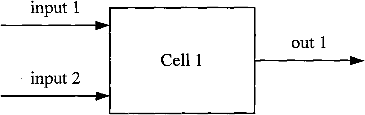
[0068] figure 1 It is a schematic circuit diagram of a logic gate structure in the prior art with two inputs and one output whose logic function cannot be changed. Such as figure 1 As shown, after the first input (input 1) and the second input (input 2) are input to the logic gate (Cell 1), an output (out 1) is generated, but the logic function of the logic gate cannot be changed.

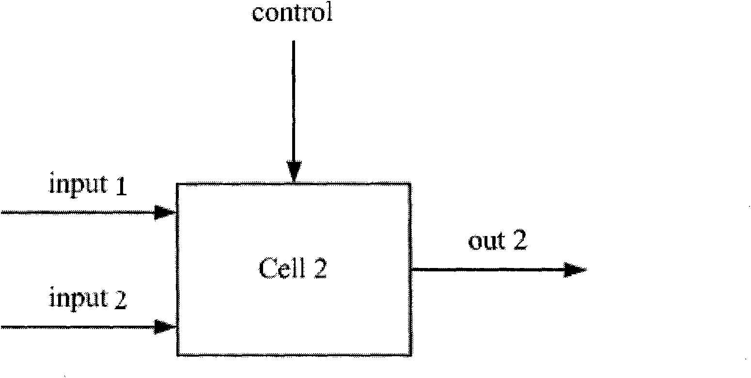
[0069] figure 2 It is a schematic diagram of the structural principle of the reconfigurable dynamic logic gate of the present invention. Such as figure 2 As shown, the first input (input 1) and the second input (input 2) are connected to the logic gate (Cell 2), and the logic gate generates an output (out 2) under the action of the control signal (control). compared to figure 1...


PUM


Abstract

The invention discloses a reconfigurable dynamic logical gate circuit which can carry out dynamic conversion among various logical functions. The circuit comprises a first input end, a second input end, a third input end, an operational circuit and an output end, wherein the first input end is used for receiving input signals; the second input end is used for receiving weighting coefficients for weighting the input signals and is also used for receiving potential well parameters; the third input end is used for receiving control instructions; the operational circuit is respectively connected with the first input end, the second input end and the third input end and is used for acquiring the logical operation results of the dynamic logical gate circuit according to the input signals, the weighting coefficients, the control instructions and the potential well parameters; and the output end is connected with the operational circuit and is used for outputting the logical operation results. The invention realizes the technology of the dynamic logical gate circuit which can carry out fast conversion among various logical functions. The technical scheme of the invention has higher logical conversion speed, and logical results are various.

Description

technical field [0001] The invention relates to the technical field of integrated circuits, in particular to a dynamic logic gate circuit based on double potential wells. Background technique [0002] An important research direction in the design of next-generation computer chips is to make computing devices have a reconfigurable dynamic logic architecture. Existing reconfigurable dynamic logic architectures are all based on traditional programmable logic gate array (FPGA) technology. FPGA technology is to reconnect static connections on integrated circuit chips to achieve different functions. Individual logic gates are not reconfigurable. However, traditional logic gate circuits are generally composed of single-selection switch circuits. The gate circuits can only be set in advance and cannot be dynamically converted. The prior art also has a binary logic gate circuit composed of a double selection switch circuit, which realizes the conversion between "AND gate" and "OR g...

Claims


Application Information

Patent Timeline
Patent Type & Authority Applications(China)
IPC IPC(8): H03K19/20
Inventor 彭海朋李丽香胡岗杨义先
Owner BEIJING UNIV OF POSTS & TELECOMM
Why Eureka
Try Eureka