
Method and device for recovering cross-domain path based on path computation element

A path calculation and path recovery technology, applied in the field of computer networks, can solve problems such as inability to restore services in time and respond to service interruptions quickly, and achieve the effects of improving user experience, reducing processing links, and saving time

Inactive Publication Date: 2011-01-12
ZTE CORP
View PDF0 Cites 15 Cited by
  • Summary
  • Abstract
  • Description
  • Claims
  • Application Information

AI Technical Summary

Problems solved by technology

[0008] In view of this, the present invention provides a cross-domain path recovery method and device based on path calculation elements, to solve the problem in the prior art that services cannot be restored in time due to inability to quickly respond to service interruptions

Method used


Image

  • Method and device for recovering cross-domain path based on path computation element
  • Method and device for recovering cross-domain path based on path computation element
  • Method and device for recovering cross-domain path based on path computation element

Examples


Embodiment 1

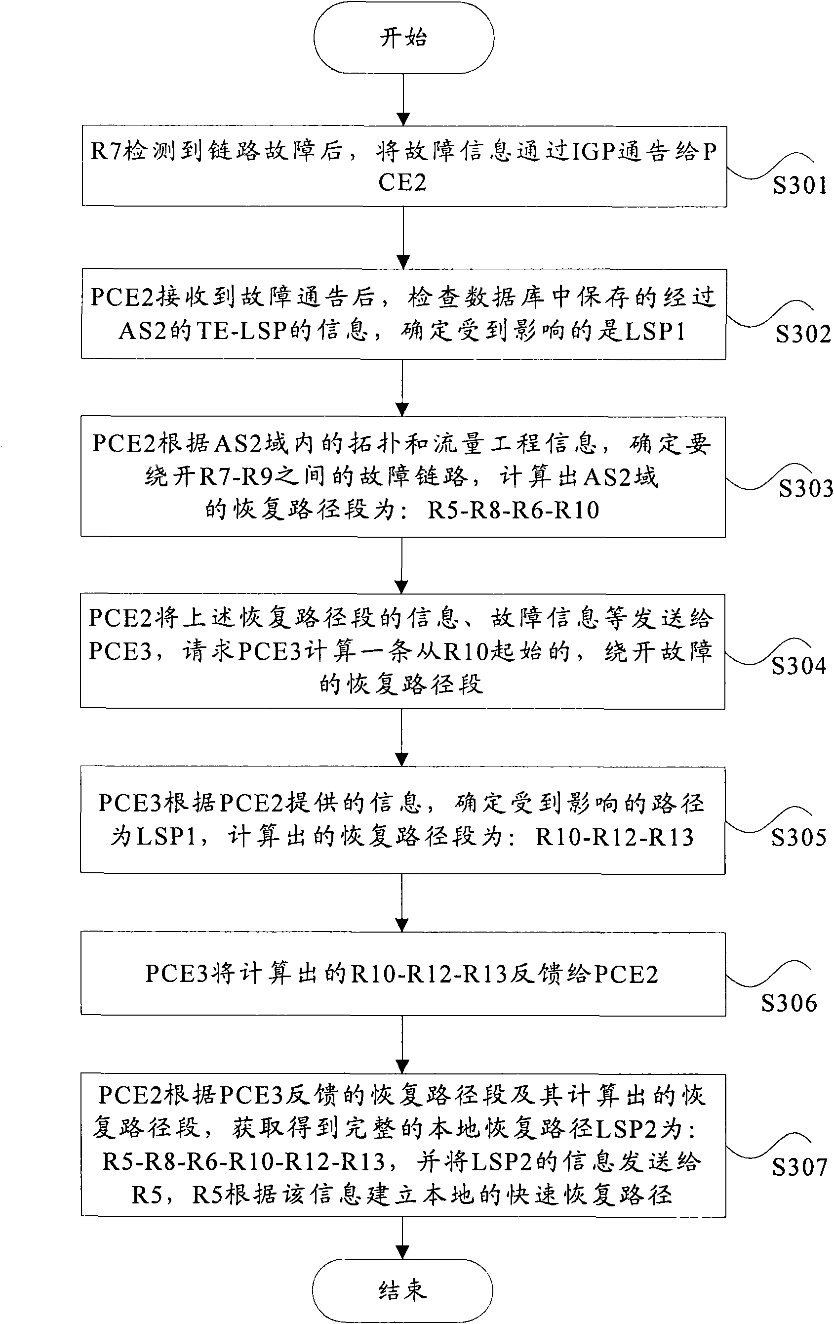
[0050] In this example, in figure 2 In the shown network, the technical solution provided by the embodiment of the present invention will be described by taking the failure of the link between R7-R9 as an example.

[0051] image 3 In this embodiment, when the link between R7-R9 fails, the flow chart is as follows image 3 As shown, in this embodiment, the calculation method of the recovery path after the failure of the link between R7-R9 mainly includes the following steps:

[0052] Step S301: After R7 detects a link failure, it notifies PCE2 of the failure information through IGP;

[0053] Step S302: After receiving the fault notification, PCE2 checks the information of the TE-LSP passing through AS2 stored in the database, and determines that the affected one is LSP1, the path segment of LSP1 in AS2 is R5-R7, and the originating end of the path is R1, the destination end is R13;

[0054] Step S303: According to the topology and traffic engineering information in the AS...

Embodiment 2

[0062] In this embodiment, it is assumed that the link between R3-R5 fails, such as Figure 5 As shown, the calculation method of the recovery path after a link failure mainly includes the following steps:

[0063] Step S501: After R5 detects a link failure, it notifies PCE2 of the failure information through IGP;

[0064] Step S502: After receiving the fault notification, PCE2 checks the information of the TE-LSP passing through AS2 stored in the database, and determines that the affected one is LSP2 (R1-R3-R5-R8-R6-R10-R12-R13), and LSP2 is in the The path segment in AS2 is R2-R5-R8, the originating end of this path is R1, and the destination end is R13;

[0065] Step S503: PCE2 determines to bypass the faulty link between R3-R5 according to the topology and traffic engineering information in the AS2 domain, the entrance must be R4, PCE3 is not required to participate in the calculation, but PCE1 is required to participate in the calculation. In this embodiment, it is assu...


PUM


Abstract

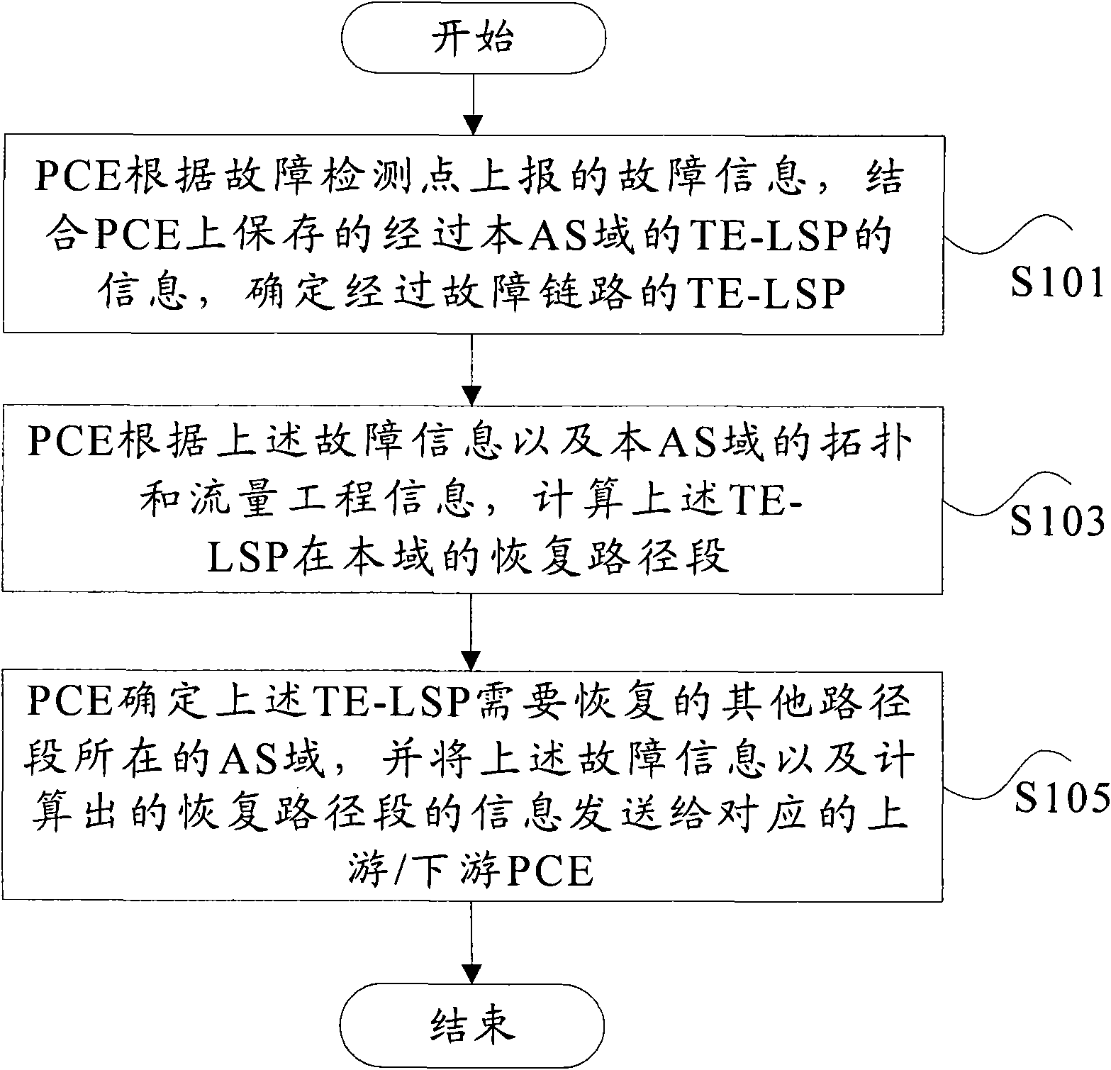
The invention discloses a method and a device for recovering a cross-domain path based on a path computation element (PCE). In the method, PCE determines a traffic engineering-label switching path (TE-LSP) which passes through a failure link by combining information on the TE-LSP which passes through an autonomous system (AS) domain and is saved by the PCE according to the failure information reported by a failure detection point; the PCE computes a recovery path section of the TE-LSP at the AS domain according to the failure information and topological traffic engineering information of the AS domain; and the PCE transmits the failure information and the related information on the computed recovery path section to upstream PCE and / or downstream PCE on a PCE sequence, so that each PCE computes the recovery path section of the TE-LSP at a neighboring AS. According to the technical scheme of the invention, the processing step in failure can be reduced, the time for recovering the service is saved and user experience is improved.

Description

technical field [0001] The invention relates to the technical field of computer networks, in particular to a method and device for restoring a cross-domain path based on a path computation unit. Background technique [0002] A path computation element (Path Computation Element, PCE for short) is an entity in an autonomous system (Autonomous System, short for short) capable of computing a path between any nodes that it can learn. In practical applications, the PCE can be integrated inside the router, or exist in the network as a separate entity, and can also be integrated with the network management system. In addition, the head-end LSR can also serve as a path computation client (Path Computation Client, PCC for short), and the PCC is used to send a path computation request to the PCE and receive a response carrying the calculated path. In practical applications, the response may also carry information in response to other requests from other PCCs. In addition, a PCE can a...

Claims


Application Information

Patent Timeline
Patent Type & Authority Applications(China)
IPC IPC(8): H04L12/56H04L12/26H04L12/24H04L12/701
Inventor 张飞鲍远林高峰
Owner ZTE CORP
Learn More