
Screen and projection system

A screen and color material technology, applied in projectors, optics, instruments, etc. with built-in screen/external screen, which can solve the problems of insufficient effect, increased screen manufacturing cost, and reduced contrast ratio.

Inactive Publication Date: 2011-01-12
SEIKO EPSON CORP
View PDF5 Cites 14 Cited by
  • Summary
  • Abstract
  • Description
  • Claims
  • Application Information

AI Technical Summary

Problems solved by technology

[0003] Conventional screens, such as reflective screens, have the following problem: while reflecting the projection light from the projector to display the projected image, they also reflect the light of the illumination, the sunlight entering from the window, etc. In bright places, the contrast, which is the brightness ratio of "white (maximum brightness)" and "black (minimum brightness)", will decrease, making it difficult to achieve clear image display
However, in such a structure, since the wavelength component before external light absorption is reflected to the viewing side (observer side) due to backscattering on the surface of the scattering layer, the effect of improving the contrast by the light-absorbing layer is not sufficient. Color purity will decrease
In addition, the scattering material contained in the scattering layer is often expensive, and the number of steps increases due to the need for a process for forming the scattering layer, which also causes an increase in the manufacturing cost of the screen.

Method used


Image

  • Screen and projection system
  • Screen and projection system
  • Screen and projection system

Examples


no. 1 Embodiment approach

[0038] Below, refer to Figure 1 ~ Figure 4 The screen of the first embodiment of the present invention will be described. In addition, in all the following drawings, in order to make the drawings easier to see, the proportions of the dimensions of the respective components are appropriately different.

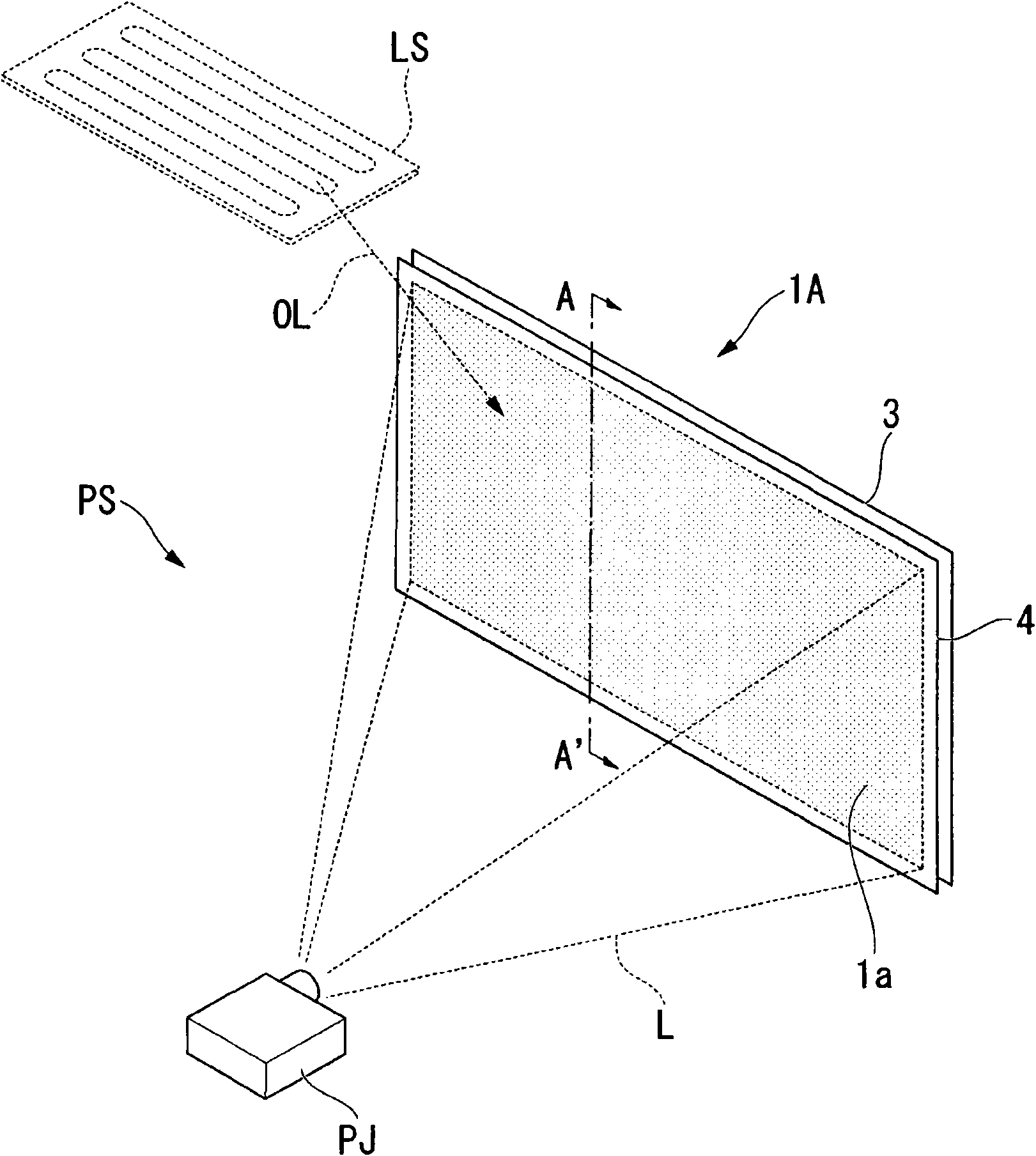
[0039] figure 1 It is a perspective view which shows the schematic structure of the screen 1A of this embodiment, and the projection system PS of this embodiment.

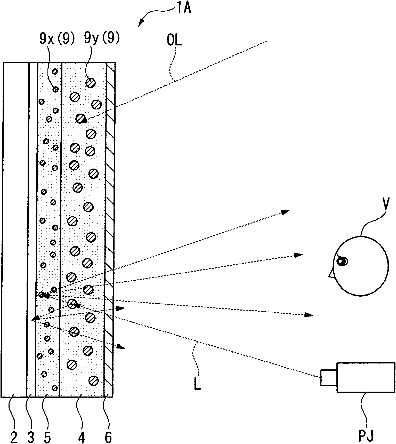
[0040] As shown in the figure, the screen 1A of this embodiment is a reflective screen, which has a first absorption and scattering layer (first color material layer) 4 and a reflection layer 3 on the projected surface 1a, and the first absorption and scattering layer 4 includes The reflective layer 3 is a color material that selectively absorbs external light OL, and is provided on the back side of the first absorbing and scattering layer 4 (opposite to the viewing side).

[0041] In addition, the screen 1A has...

no. 2 Embodiment approach

[0094] Figure 5 It is explanatory drawing of the screen 1B of 2nd Embodiment of this invention. The screen 1B of this embodiment is partly the same as the screen 1A of the first embodiment. The difference is that the color material dispersed in the second absorption-scattering layer 5 is the same as the color material 9y dispersed in the first absorption-scattering layer 4, and in the first absorption-scattering layer 4 and the second absorption-scattering layer 5, the color The concentration of material 9y is different. Therefore, the same reference numerals are assigned to the same components in this embodiment as those in the first embodiment, and detailed description thereof will be omitted.

[0095] As shown in the figure, in the second absorption-scattering layer 5 of the present embodiment, color materials 9y having a size to scatter light in the visible light region are dispersed. In addition, when the first absorption-scattering layer 4 is compared with the second...


PUM


Abstract

The invention aims at providing a screen and a projection system capable of reducing manufacture procedure and used for obtaining image with improved contrast ratio with lower cost. A screen includes: a substrate 2; and a first color material layer 4 disposed on one surface of the substrate 2, wherein the first color material layer 4 includes a first color material 9y adapted to absorb light with a part of wavelengths of an incident light, and the first color material 9y has a peak absorption wavelength in a visible light range, and a size of causing Mie scattering on the light in the visible light range.

Description

technical field [0001] The invention relates to screens and projection systems. Background technique [0002] Conventionally, various screens have been used as projection surfaces of enlarged images for exhibitions using projectors (projection-type display devices), exhibitions at academic institutions, etc., and video viewing at home theaters. [0003] Conventional screens, such as reflective screens, have the following problem: while reflecting the projection light from the projector to display the projected image, they also reflect the light of the illumination, the sunlight entering from the window, etc. In bright places, the contrast ratio of "white (maximum brightness)" to "black (minimum brightness)" will decrease, making it difficult to display clear images. Therefore, the development of screens for the purpose of achieving high contrast in bright rooms by reducing the minimum luminance by suppressing the influence of external light that causes contrast reduction, s...

Claims


Application Information

Patent Timeline
Patent Type & Authority Applications(China)
IPC IPC(8): G03B21/60G03B21/10
CPCG03B21/56
Inventor 冈本纯一
Owner SEIKO EPSON CORP
Learn More