
Grate firing equipment

A fire bed combustion and fire bed technology, which is applied in the directions of combustion equipment, combustion methods, lighting and heating equipment, etc., can solve the problems of easy burnout and complex structure of the grate

Active Publication Date: 2015-05-20
蒋钧
View PDF9 Cites 0 Cited by
  • Summary
  • Abstract
  • Description
  • Claims
  • Application Information

AI Technical Summary

Problems solved by technology

[0009] In 1993, the inventor proposed the utility model technology of "boiler multi-layer fire bed combustion equipment", the patent number is 932351360, which realized the first two advantages, but did not realize the third one because of the complex structure and the easy burnout of the grate. advantage

Method used


Image

  • Grate firing equipment

Examples


Embodiment Construction

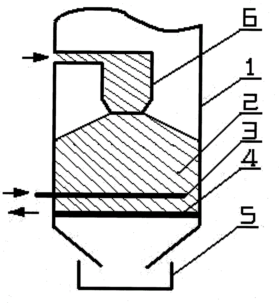
[0017] The solid fuel is pushed into the fuel preheating tank (6), and is preheated and dry-distilled in an oxygen-deprived state to precipitate moisture and volatile matter. As the fire bed layer moves down, the fuel falls on the burning fire bed surface, is quickly ignited in a "double-sided fire" manner, and starts to burn. The burning fuel creates a high temperature bed in the furnace, which is supported by the lower grate plate (4).

[0018] After the fire bed burns for a period of time, a layer of burnt ash layer is formed at the bottom of the fire bed.

[0019] Insert the upper grate plate (3) into the hearth so that the ash layer is separated from the fire bed and supports the fire bed.

[0020] The lower fire grate plate (4) is extracted out of the furnace, so that the ash layer loses support and falls into the ash box (5) outside the furnace.

[0021] Reinsert the lower grate plate (4) into the furnace chamber. Pull the upper grate plate (3) out of the furnace,...


PUM


Abstract

The invention provides grate firing equipment suitable for a solid fuel boiler, a waste incinerator, a heat furnace and a range. In the equipment, a fuel pre-heat tank is arranged in a hearth above a grate layer and is heated and baked by flame in the hearth; the fuel inside the fuel pre-heat tank is preheated and subject to the destructive distillation in an anaerobic state to separate moisture and volatile; and the fuel falls on the grate layer, and is oxidized by air in the hearth to fire. Furthermore, two grate plates which are parallel to each other and can be plugged are arranged on the bottom of the hearth, and the separation of the fuel and ashes and slagging can be realized by alternately plugging in and out the two grate plates. The grate firing equipment realizes mechanical, simple and reliable slagging function of the grate firing furnace, and simultaneously maintains the firing property of 'double-sided firing' to ensure that the grate furnace is applicable to various solid fuels, and has the advantages of sufficient firing, small pollution and good effect of smoke prevention and dust control.

Description

technical field [0001] The invention proposes a technology suitable for fire bed combustion equipment of boilers, garbage incinerators, heating furnaces and stoves. Background technique [0002] In the combustion equipment of boilers, incinerators, heating furnaces and stoves, the fire bed furnace is an important combustion equipment. Furnaces, hand-fired furnaces, push-feed furnaces, fixed grate furnaces, vibrating grate furnaces, rolling grate furnaces, etc. The reason why it is subdivided into so many furnace types is to adopt different furnace types for different fuels and equipment capacities to achieve better economy and combustion effect. [0003] With the development of biomass solid fuel and the incineration of solid waste, the society needs a better fire bed combustion equipment, which should have the following three advantages at the same time: [0004] 1. It has the combustion characteristics of "two-sided ignition" and is suitable for all solid fuels. [00...

Claims


Application Information

Patent Timeline
IPC IPC(8): F23K1/04F23J1/00
Inventor 蒋钧
Owner 蒋钧
Learn More