


Quick Research
Generate reliable direction feasibility study reports for your R&D in just a few steps.

Technical Q&A
Discover and master advanced knowledge NOW. Basics, ideas, possibilities, all at once.

Find Solutions
As an expert in R&D theories, this can generate solutions to your technical problems instantly.

Evaluate Feasibility
Analyze your overall solution with one click, know your potential R&D risks in advance.

Monitor Landscape
Get weekly tech updates, stay abreast of the latest tech innovations and key insights.
Synchronous motor brushless excitation device realized by adopting switching power supply
A technology for synchronous motors and switching power supplies, which is applied in electromechanical devices, asynchronous induction motors, and control generators through magnetic field changes. It can solve the problems of canceling brushes and slip rings, complex structures, and not replacing brushes and slip rings. Achieve the effect of low loss and simple structure
- Summary
- Abstract
- Description
- Claims
- Application Information
AI Technical Summary
Problems solved by technology
Method used
Image

Examples
Embodiment 1
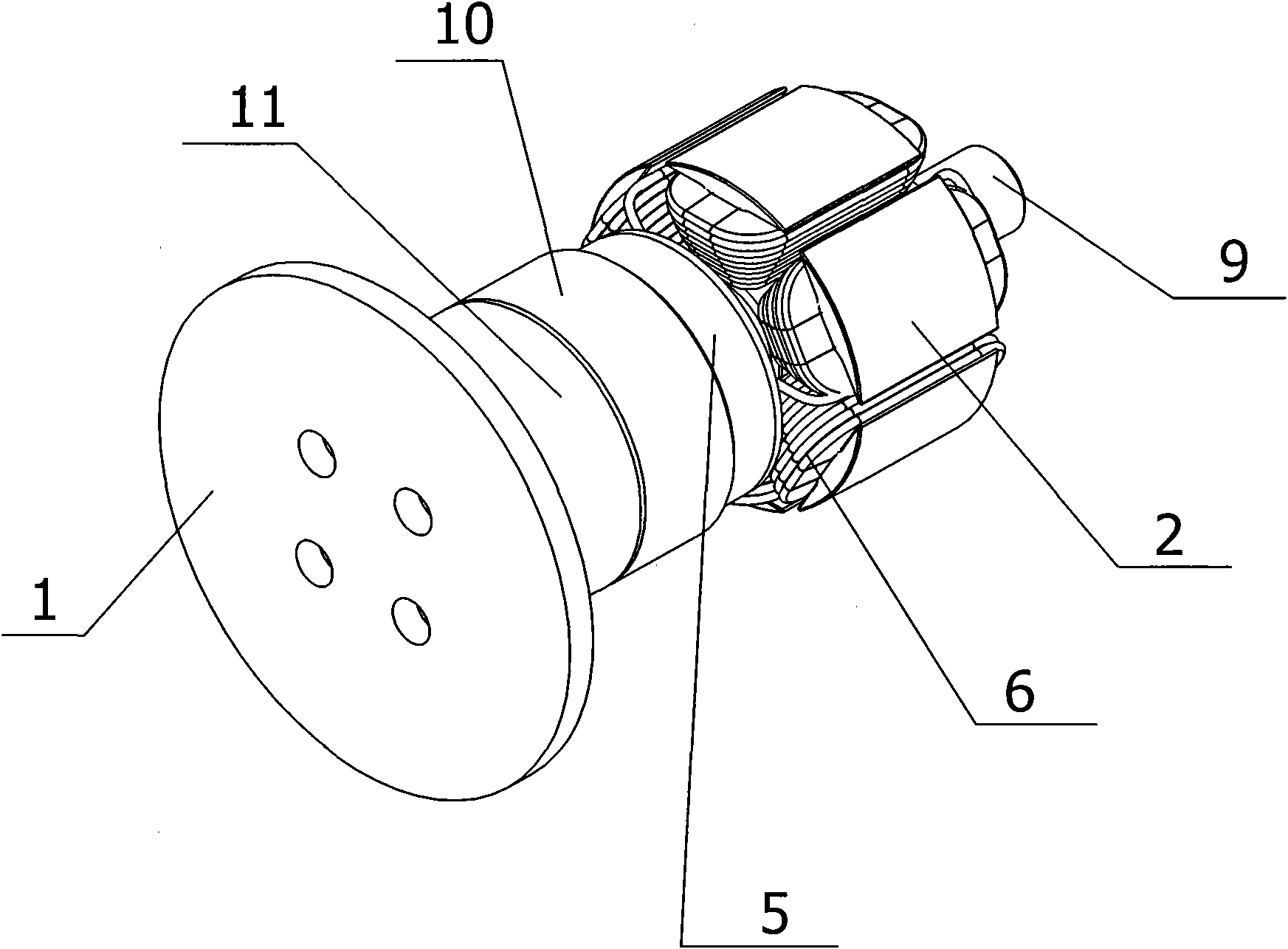
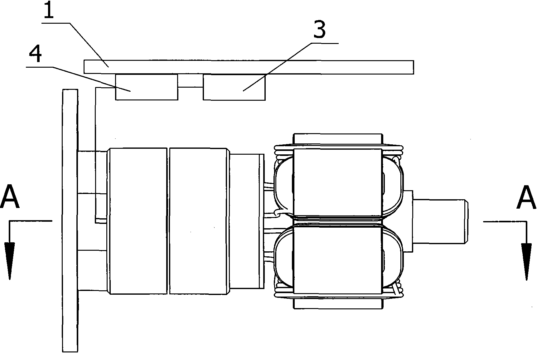
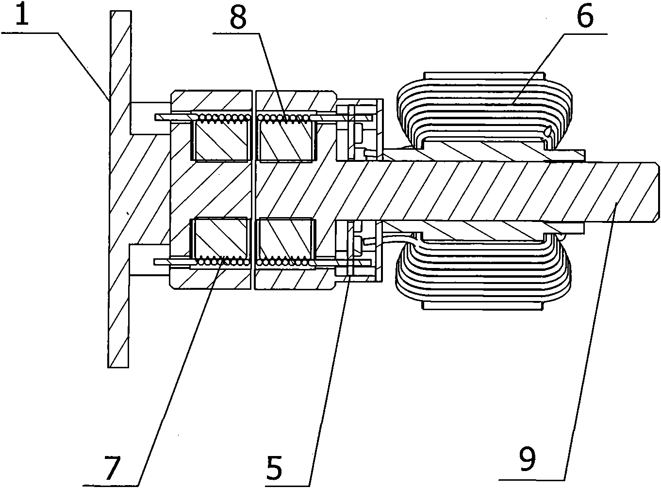
[0023] A brushless excitation device for a synchronous motor is realized by using a switching power supply, and its composition includes: a stator 1 and a rotor 2 of a synchronous motor, a controller 3 is installed inside the stator, the controller is connected to an inverter 4, and the inverter The transformer is connected to the magnetic tank transformer, and the magnetic tank transformer is connected to the rectifier 5, and the rectifier is connected to the excitation winding 6, and the excitation winding is wound on the iron core of the rotor.
[0024] The brushless excitation device for a synchronous motor is realized by using a switching power supply, the magnetic tank transformer includes a primary coil 7 installed on the stator, the primary coil is coupled to a secondary coil 8 through an air gap, and the The secondary coil is mounted on the shaft 9 of the rotor.
[0025] The brushless excitation device of the synchronous motor is realized by using a switching power su...
Embodiment 2
[0027] as attached Figure 1-3 As shown, the secondary iron core 10 of the magnetic tank transformer and the rectifier are coaxially arranged with the motor rotor iron core and the field winding. The other part of the switching power supply is installed on the stator of the synchronous motor, the controller and the inverter are placed in the cavity of the stator shell, the common DC bus is arranged on the inner surface of the stator shell, and the primary iron core 11 of the magnetic tank transformer is fixed at the end of the motor stator , and is opposite to the secondary iron core of the magnetic tank transformer, and the gap between the primary and secondary iron cores is about 0.5mm. The secondary coil of the magnetic tank transformer is wound inside the secondary core, and the primary coil is wound inside the primary core.
[0028] as attached Figure 4 As shown, the controller completes the control of the inverter under the power supply of the DC bus voltage, outputs ...
PUM
 Abstract
Description
Claims
Application Information
 - R&D Engineer
- R&D Manager
- IP Professional
- Industry Leading Data Capabilities
- Powerful AI technology
- Patent DNA Extraction
Browse by: Latest US Patents, China's latest patents, Technical Efficacy Thesaurus, Application Domain, Technology Topic, Popular Technical Reports.
© 2024 PatSnap. All rights reserved.Legal|Privacy policy|Modern Slavery Act Transparency Statement|Sitemap|About US| Contact US: help@patsnap.com