Electromotor with brushes

A technology of electric motors and brushes, applied in the direction of electric components, electrical components, electromechanical devices, etc., can solve problems such as poor power supply, achieve the effects of reducing noise, reducing poor power supply, and improving durability

Active Publication Date: 2010-12-22
MABUCHI MOTOR
View PDF4 Cites 5 Cited by
  • Summary
  • Abstract
  • Description
  • Claims
  • Application Information

AI Technical Summary

Problems solved by technology

This gas is decomposed by the heat energy generated by the sparks generated when the carbon brushes on the commutator face are energized and switched, and the decomposed silicon dioxide SiO2 as an insulator 2 Adhering to the commutator surface, resulting in poor electrical conduction

Method used


Image

  • Electromotor with brushes
  • Electromotor with brushes
  • Electromotor with brushes

Examples


Embodiment Construction

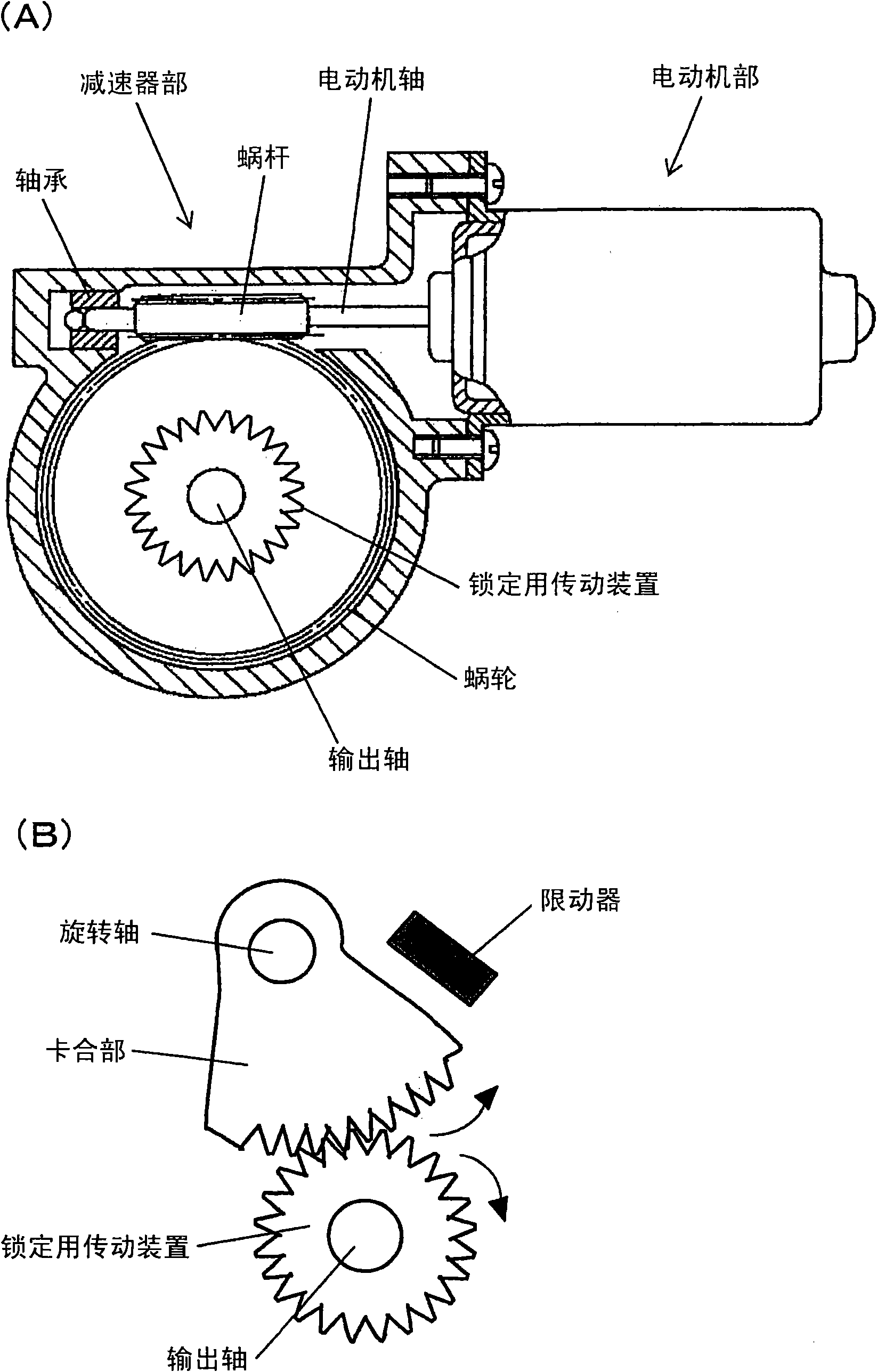
[0038] figure 1 It is a diagram illustrating a mechanical unit with a stop mechanism to which the present invention can be applied, (A) is an overall view of a brushed motor showing a worm reducer part in section, and (B) is an enlarged cross-sectional view showing a stop mechanism part. exist figure 1 In (A), the motor part is attached to the speed reducer part, and the front end part of the motor shaft is supported by the bearing shaft of the speed reducer part. The worm is fixed to the motor shaft. The worm wheel is meshed with the worm, so that the driving torque output from the motor part is transmitted from the motor shaft to the worm, and the driving torque is transmitted from the worm to the worm wheel in the speed reducer part, and the torque is taken out from the output shaft to the outside.

[0039] In the brushed motor shown in the figure, the stop mechanism includes: a locking actuator fixed to the output shaft and rotating together with the output shaft; an ...


PUM


Abstract

The invention provides an electromotor with brushes capable of reducing locking noise made by the vibration of the electromotor when the power supply to the electromotor is cut off, causing the electromotor to stop working. The invention is co-used with a stopping mechanism capable of making the electromotor stop rotating. The brush gear comprises a pair of brushes, a pair of brush arms maintaining the brushes, and a pair of brush substrates integrated with the brush arms respectively. The connecting end part between the brush arms and the brush substrates is fixed to an end cover, and the brush arms takes advantage of its elasticity to make brushes capable of moving in a radial direction along with communicators slidingly contacted with the brushes. With the curve processing part arranged at one side of the brush arm foot, the brushes can also move in a tangential direction along with communicators slidingly contacted with the brushes.

Description

technical field [0001] The present invention relates to a brushed motor that reduces noise generated when a motor rotating machine is stopped by a stop mechanism. Background technique [0002] Among small electric motors widely used in electric equipment for automobiles such as door lock opening and closing devices for automobiles and electric mirror storage devices, there are known electric motors that are driven by turning on the power supply for a predetermined time. Such a small motor is stopped by a mechanical stopper before power is turned off after performing a motor function such as a motor vehicle door lock. Usually, in order to reliably complete the function of the motor under various conditions, the power on time of the motor is set so that after the motor is stopped (motor locked) by the mechanical stopper, the power is turned off after a short period of time. . In other words, there is a period during which power is supplied to the small motor after it is stop...

Claims


Application Information

Patent Timeline
Patent Type & Authority Applications(China)
IPC IPC(8): H02K5/14
Inventor 山崎博嗣三田俊吉木村亮一马渊朋也
Owner MABUCHI MOTOR
Why Eureka
Try Eureka