Device for plugging valves of pressure vessel

A technology for pressure vessels and valves, applied to valve devices, engine components, mechanical equipment, etc., can solve problems such as complicated operation and redundant equipment, and achieve the effects of simple operation, good plugging effect, and small weight

Active Publication Date: 2010-12-22
金雹峰 +2
View PDF0 Cites 0 Cited by
  • Summary
  • Abstract
  • Description
  • Claims
  • Application Information

AI Technical Summary

Problems solved by technology

[0007] The purpose of the present invention is to provide a pressure vessel valve plugging device, which solves the problems of redundant equipment and complicated operation of existing plugging devices

Method used


Image

  • Device for plugging valves of pressure vessel
  • Device for plugging valves of pressure vessel
  • Device for plugging valves of pressure vessel

Examples


Embodiment Construction

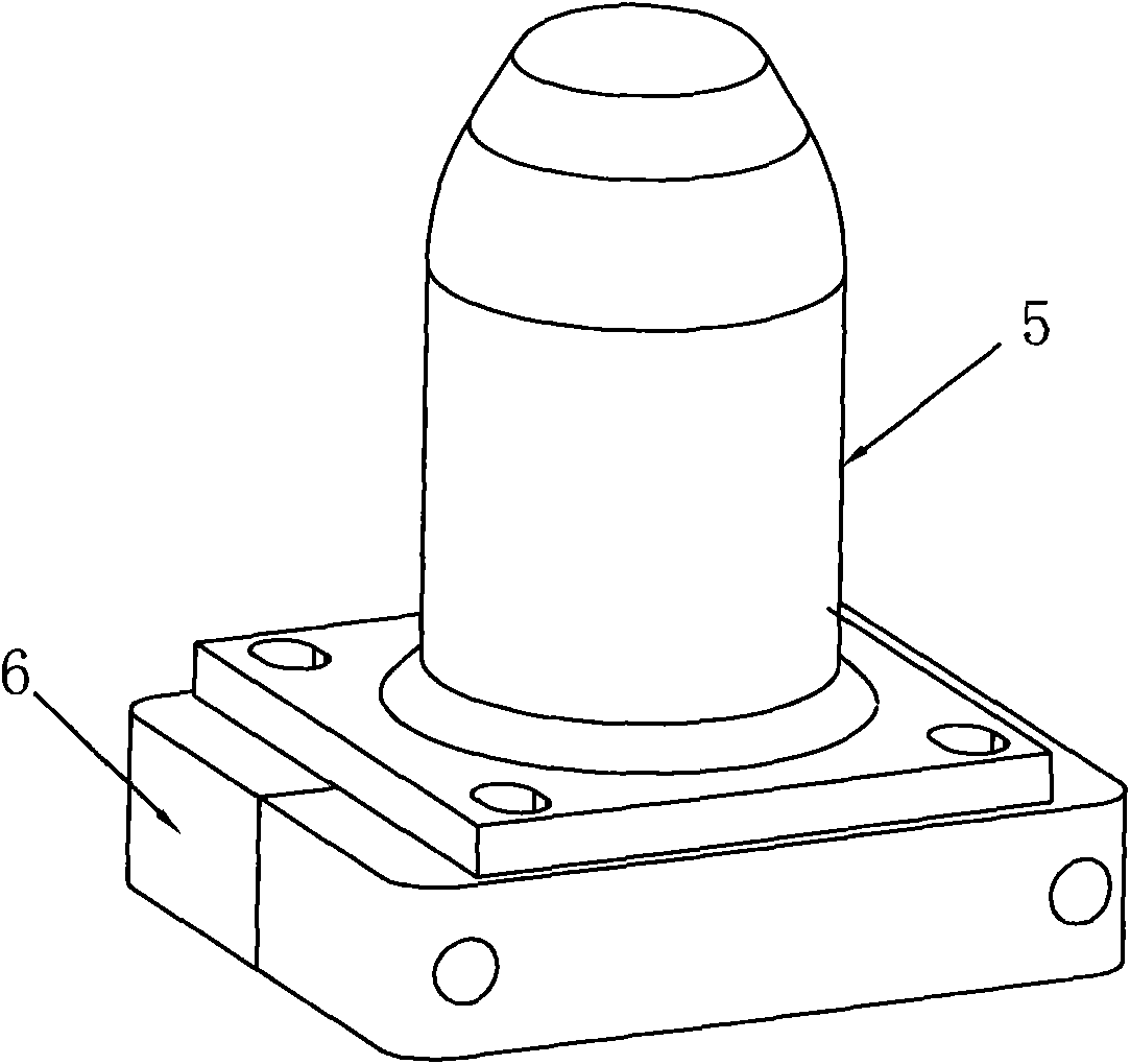
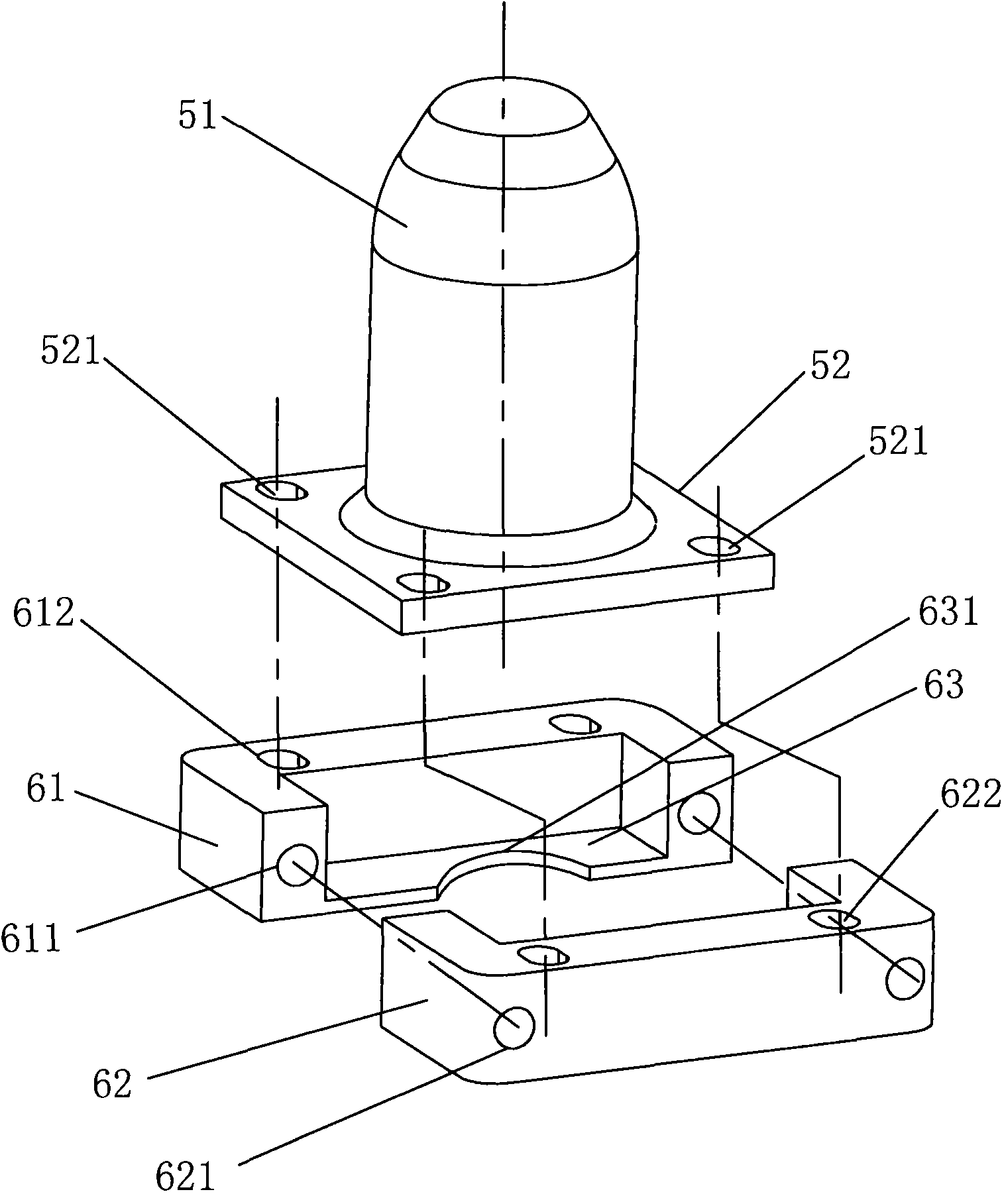
[0028] like figure 2 , image 3 As shown, it is a three-dimensional assembly view and an exploded view of a pressure vessel valve leak plugging device of the present invention, which includes two parts: a cover body 5 and a seat body 6, wherein:

[0029] The cover 5 includes an integrally connected airtight cover 51 and an upper cover 52, the airtight cover 51 is provided with an opening, and the upper cover 52 is connected to the opening of the airtight cover 51, The upper cover plate 52 is provided with several connecting holes 521, which are used for fastening connection with the seat body 6; in addition, in order to ensure the airtight effect of the leakage plugging device, a sealing ring 53 ( See Figure 4 );

[0030] The seat body 6 includes a left base 61 and a right base 62 which are arranged oppositely, and a lower bottom plate 63 is extended on the left base 61 and the right base 62 respectively, and the lower bottom plate 63 is used to abut against the valve On...


PUM


Abstract

The invention provides a device for plugging valves of a pressure vessel, comprising a base and covers, wherein the base comprises a left base and a right base which are oppositely arranged; lower bottom plates oppositely extend from the left base and the right base; the left base and the right base are respectively sleeved at the two sides of valve mounting bases of the pressure vessel and are fixedly connected; the lower bottom plates push against the lower surfaces of the valve mounting bases; the covers comprise enclosed covers and upper cover plates which are integrally connected; the enclosed covers are provided with openings; the upper cover plates are connected in the opening positions of the enclosed covers; the enclosed covers cover the valve mounting bases from top; the upper cover plates and the base are fixedly connected; sealing rings are arranged in the enclosed covers and are sealed between the enclosed covers and the valve mounting bases. The device is simple in structure and convenient to operate, saves the plugging time and improves the sealing effect.

Description

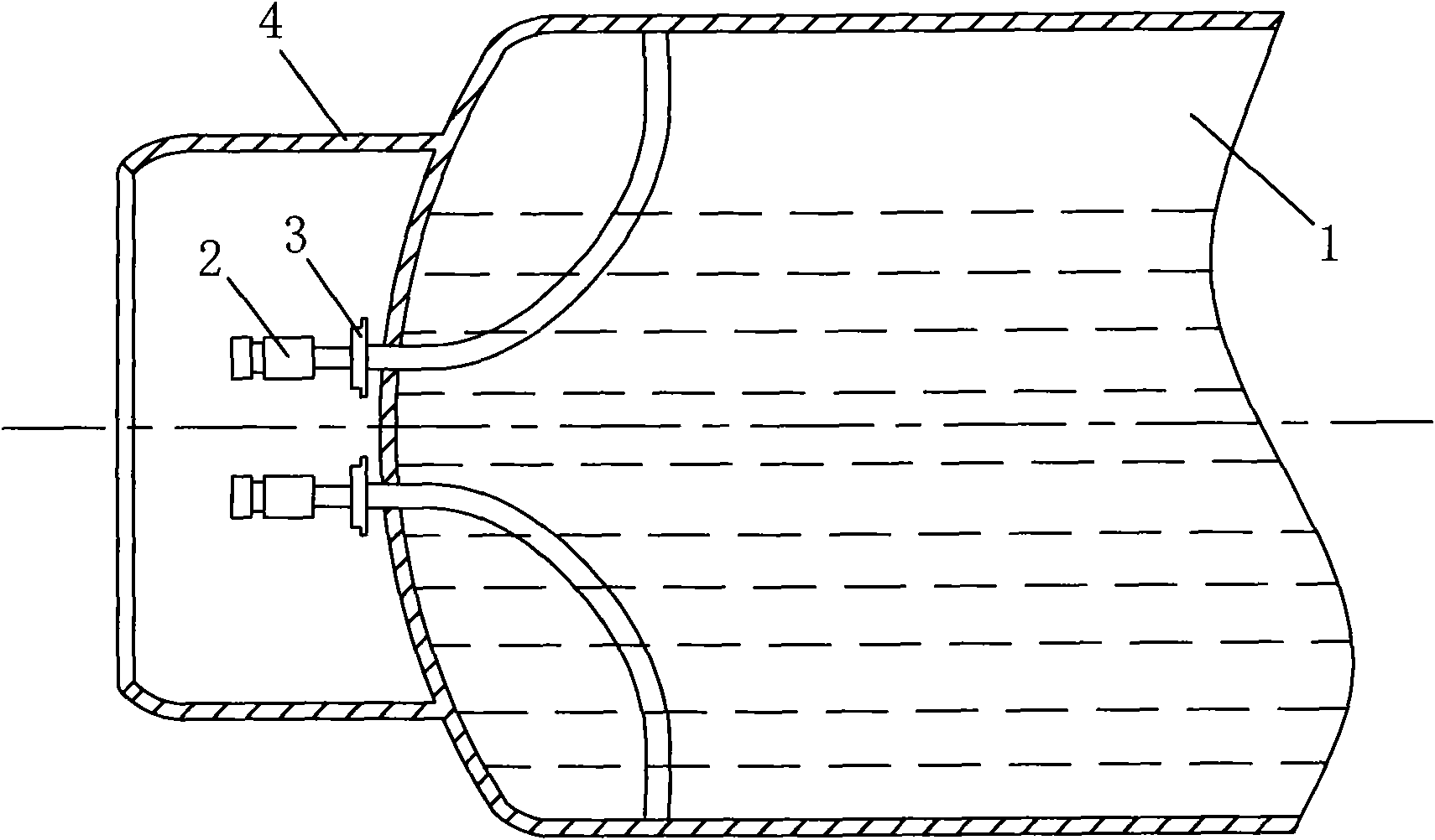
technical field [0001] The invention relates to a leak-stopping device, in particular to a device for leak-stopping a valve of a pressure vessel. Background technique [0002] Pressure vessels holding hazardous chemicals such as figure 1 The liquid chlorine tank 1 shown is generally equipped with two shut-off valves 2, which are used to control the opening and closing of the pressure vessel. In order to prevent the damage of the shut-off valve 2 from shortening the service life of the pressure vessel, a valve mounting seat 3 is installed between the shut-off valve 2 and the pressure vessel. to combine figure 1 , figure 2 As shown, the valve mounting seat 3 is screwed on the liquid chlorine tank 1, and a gap of several centimeters is reserved between the surface of the liquid chlorine tank 1, and the shut-off valve 2 is screwed on the valve mounting seat 3, to communicate with liquid chlorine tank 1. In order to prevent the shut-off valve 2 from leaking due to accidenta...

Claims


Application Information

Patent Timeline
Patent Type & Authority Applications(China)
IPC IPC(8): F16K51/00
Inventor 金雹峰金融金盈
Owner 金雹峰
Why Eureka
Try Eureka