Carrying device

A bearing device and bearing platform technology, applied in ion implantation plating, metal material coating process, coating and other directions, can solve the problem that the uniformity of the film layer cannot be guaranteed

Inactive Publication Date: 2013-03-20
HONG FU JIN PRECISION IND (SHENZHEN) CO LTD +1
View PDF0 Cites 2 Cited by
  • Summary
  • Abstract
  • Description
  • Claims
  • Application Information

AI Technical Summary

Problems solved by technology

Therefore, the uniformity of the film layer formed in the above-mentioned coating process cannot be guaranteed

Method used


Image

  • Carrying device
  • Carrying device
  • Carrying device

Examples


Embodiment Construction

[0012] The carrying device provided by the technical solution will be further described in detail below in combination with multiple embodiments and multiple drawings.

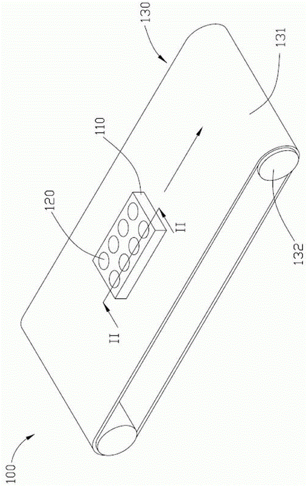
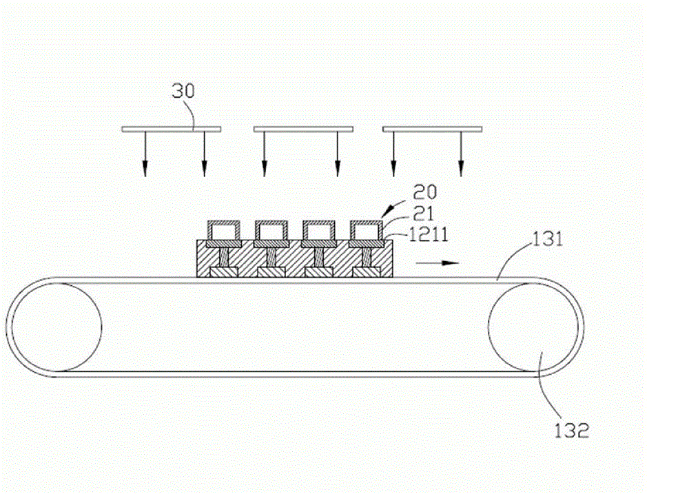
[0013] Please also refer to figure 1 and figure 2 , a bearing device 100 provided in the first embodiment of the technical solution, which includes a base 110 , a plurality of rotating bearing platforms 120 and a conveying device 130 .

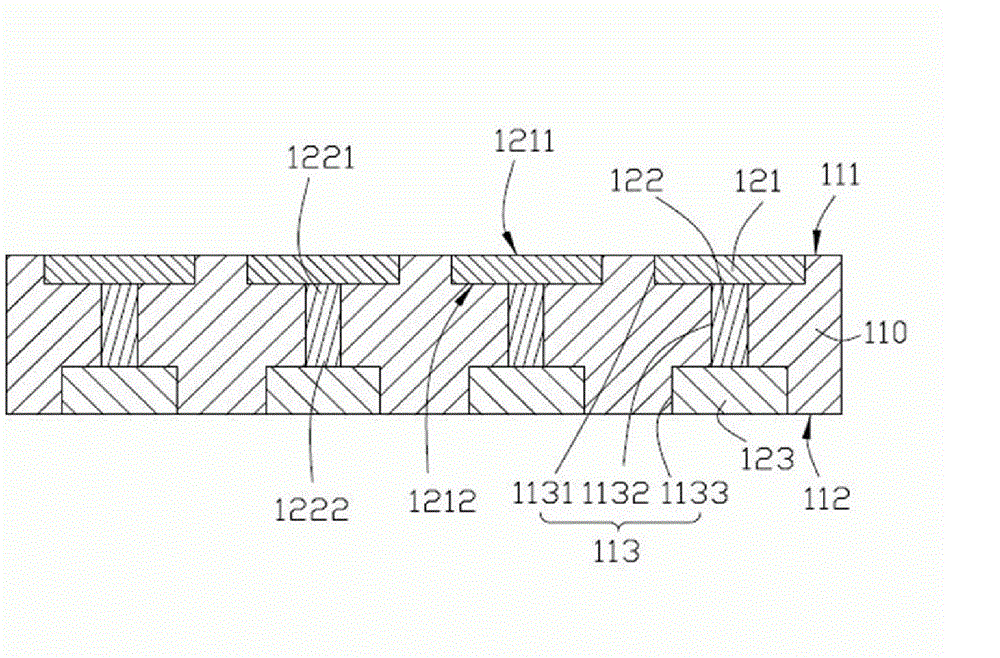
[0014] The base 110 has a plate-like structure, which can be rectangular, circular or other shapes. In this embodiment, the base 110 is in the shape of a rectangular plate, which includes a top surface 111 and a bottom surface 112 opposite to the top surface 111 . The top surface 111 and the bottom surface 112 are parallel to each other and both are planes. A plurality of receiving holes 113 are defined from the top surface 111 to the bottom surface 112 . In this embodiment, the base 110 is provided with eight receiving holes 113 , and the eight receiving holes 113 are ar...


PUM


Abstract

The invention provides a carrying device which is used for carrying out continuous sputtering on a workpiece. The carrying device comprises a plurality of rotary carrying platforms, a base and a conveying device, wherein the rotary carrying platforms are installed on the base; each rotary carrying platform is provided with a carrying surface for carrying the workpiece and driving the workpiece placed on the carrying surface to rotate relative to the base around an axis which is perpendicular to the carrying surface; and the base is arranged at the conveying device, and the conveying device is used for driving the base and the rotary carrying platforms to move.

Description

technical field [0001] The invention relates to the field of vacuum sputtering, in particular to a carrying device for continuous sputtering. Background technique [0002] Sputtering is a thin-film physical vapor deposition technology. The continuous sputtering (In-line Sputtering) coating process has the advantages of fast speed, high output, good coating quality, and strong film adhesion. It has been widely used in industry. For the mass production of various metal and non-metal film layers, please refer to Effects of Target Structure Onthe Properties of MO Recording in document IEEE Transactions OnMagnetics, Vol.24, No.6, 2772-2774 (1988) by E.Schultheiβ et al. Media Produced in a Large-Scale Vertical In-LineSputtering system article. [0003] Before the lens module is assembled, it is necessary to coat the outer surface of the mirror base with an anti-electromagnetic interference film to reduce the influence of electromagnetic interference on the assembled lens module. ...

Claims


Application Information

Patent Timeline
Patent Type & Authority Patents(China)
IPC IPC(8): C23C14/56C23C14/34
Inventor 蔡泰生
Owner HONG FU JIN PRECISION IND (SHENZHEN) CO LTD
Why Eureka
Try Eureka