Method and device for mounting piezoelectric wafer used for structure health monitoring

A piezoelectric chip, health monitoring technology, applied in the direction of measuring devices, machine/structural component testing, instruments, etc., can solve the problem of difficult to find and replace, unsuitable thin shell structure, bonding interface and piezoelectric chip life-span structure Life expectancy and other issues to achieve the effect of improving monitoring and diagnosis efficiency, realizing structural health monitoring, and ensuring repeatability and uniformity

Inactive Publication Date: 2010-12-15
DALIAN UNIV OF TECH
View PDF4 Cites 8 Cited by
  • Summary
  • Abstract
  • Description
  • Claims
  • Application Information

AI Technical Summary

Problems solved by technology

The existing installation methods of piezoelectric wafers include sticking type and embedded type. With these two methods, once the arrangement position of piezoelectric wafers is determined, it cannot be changed. If the number of sensors is not enough, The damage in some parts cannot be detected, that is, there are monitoring blind spots
These two methods also have the following problems: 1) the bonding interface is not uniform, resulting in uneven energy transfer between the piezoelectric wafer and the structure to be tested, thus requiring a large number of experiments to check; 2) the bonding interface and the piezoelectric wafer The service life is lower than that of the structure and cannot be replaced; 3) The position of the sensor is fixed, so a large number of sensors are required to cover the entire structure to be tested, resulting in an increase in the weight of the structure; 4) The embedded installation method generally integrates the piezoelectric chip into the structure, Compromises structural integrity and is not suitable for thin shell structures, if the sensor fails, it is not easy to find and replace

Method used


Image

  • Method and device for mounting piezoelectric wafer used for structure health monitoring
  • Method and device for mounting piezoelectric wafer used for structure health monitoring
  • Method and device for mounting piezoelectric wafer used for structure health monitoring

Examples


Embodiment 1

[0042] Embodiment 1, a method and device for installing a piezoelectric wafer for structural health monitoring.

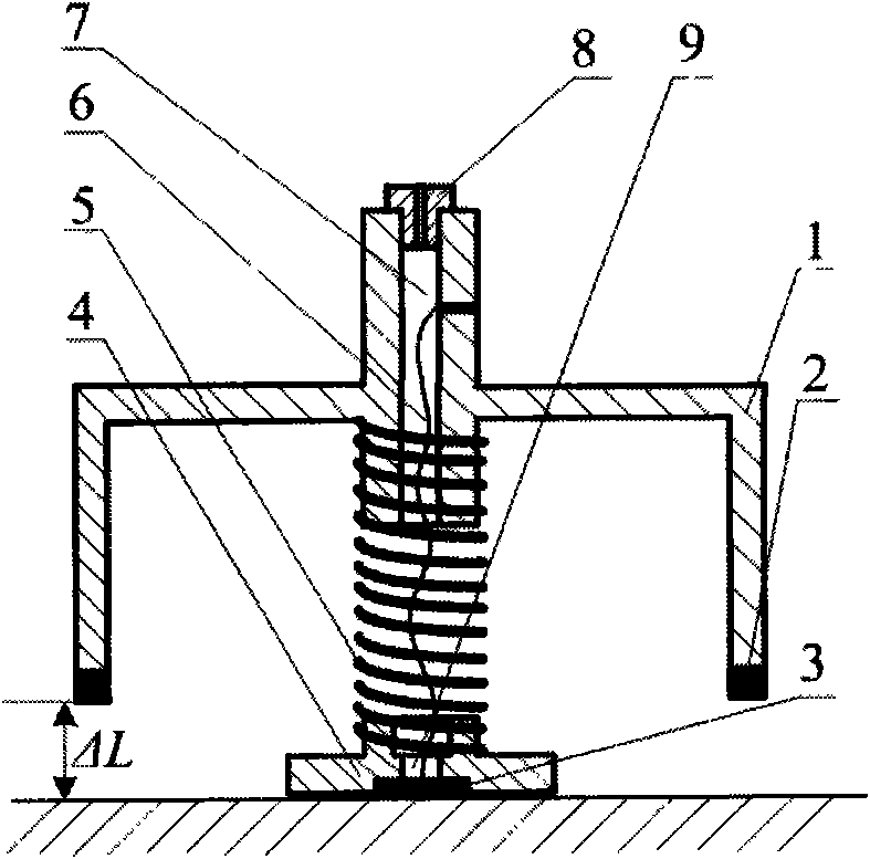
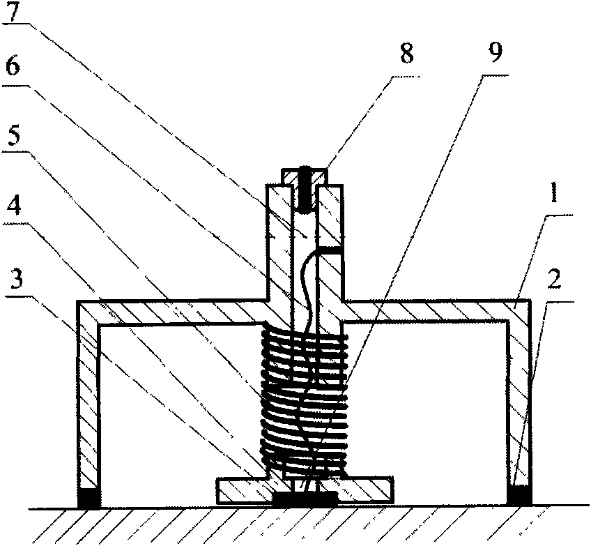
[0043] Such as figure 1 As shown, it is composed of concave cavity hard body 1, concave cavity adsorption software 2, piezoelectric chip 3, piezoelectric chip seat 4, and spring 5; the inner and outer surfaces of concave cavity hard body 1 and piezoelectric chip seat 4 The connection springs are in the form of hollow bosses, and the springs are sheathed on the bosses; the centers of the bosses are respectively provided with an air hole 7 and a connecting wire through hole 9, and the air hole 7 is equipped with an air nozzle 8. The lead-through part is sealed with polyurethane material.

[0044] The piezoelectric wafer seat 4 is provided with a groove for placing the piezoelectric wafer, and its depth is smaller than the thickness of the piezoelectric wafer.

[0045] The opening surface and the upper surface of the concave cavity are circular, with a radius of 1.7...

Embodiment 2

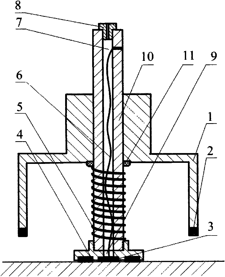
[0048] Example 2, a device with hollow guide rods for mounting piezoelectric wafers for structural health monitoring.

[0049] Such as image 3 , Figure 4 As shown, a hollow guide rod 10 stretching out from the concave cavity is provided between the piezoelectric wafer base 4 and the concave cavity hard body 1, and the hollow guide rod 10 is fixedly connected with the piezoelectric wafer base 4, and is connected with the concave cavity. A sealing ring 11 is installed between the cavity hard bodies 1, the concave cavity hard body 1 and the sealing ring 11 can move along the hollow guide rod 10, the spring 5 is set on the hollow guide rod 10, and the hollow guide rod extends out of the concave cavity The hollow part is air hole 7, and air nozzle 8 is housed.

[0050] The structure of the piezoelectric wafer seat 4 is as Figure 10 , Figure 11 As shown, one side is arranged with 5 grooves for placing piezoelectric wafers, wherein a circular groove 22 is at the center, and 4...

Embodiment 3

[0053] Embodiment 3, the piezoelectric chip installation method and its device using a closed piston.

[0054] Such as Figure 5 , Figure 6 , Figure 7 Shown, the device of installing piezoelectric chip is as embodiment 1, but the piston barrel 13 of airtight piston is housed on the concave cavity hard outer surface, seals with gasket 12, and air hole 7 is communicated with piston. The structure of the piezoelectric wafer seat is the same as in Embodiment 2.

[0055] The connecting rod of piston 14 passes through the central through hole of piston handle 15, then fixes with nut 16, can make piston handle rotate flexibly. The piston handle 15 is placed in the two U-shaped grooves 17 on the piston barrel 13 before being pulled, and the piston 14 is pulled outward until the piston handle moves out of the U-shaped groove, and then the piston handle 15 is turned so that it is stuck on the edge of the piston barrel 13. The position of the piston can be fixed, so that the piston...


PUM


Abstract

The invention belongs to the field of sensors used for structure health monitoring, and relates to a method and a device for mounting a piezoelectric wafer used for the structure health monitoring. The method is characterized in that: the piezoelectric wafer is placed between a piezoelectric wafer seat and the surface of a monitored structure; a concave chamber of which an opening is partially attached to the surface of the monitored structure is used for buckling the piezoelectric wafer seat therein and pressing the piezoelectric wafer seat on the surface of the monitored structure through a spring inside the concave chamber to make the piezoelectric wafer tightly attached to the surface of the monitored structure; and the shell of the concave chamber is made of sealing materials and is provided with sealable air holes through which the air pressure inside a sealed chamber is reduced to make the concave chamber tightly adsorbed to the surface of the monitored structure. The method and the device adopt a vacuum adsorption mounting way, so that the piezoelectric wafer can be dismounted, replaced and moved conveniently; and the pressing force of the piezoelectric wafer has repeatability and uniformity so as to realize maneuverable structure health monitoring and improve monitoring and diagnosis efficiency.

Description

technical field [0001] The invention belongs to the field of sensors for structural health monitoring, and relates to a method and a device for installing piezoelectric wafers for structural health monitoring. Background technique [0002] Structural health monitoring is an online non-destructive testing technology, which is widely used in aerospace, civil machinery and other engineering structures to detect structural damage and damage in time, improve structural safety, prolong product service life, and reduce operation and maintenance costs. [0003] The existing structural health monitoring system is mainly composed of the following parts: 1) A sensor with a piezoelectric chip as the core component for transmitting and receiving detection signals; 2) a data acquisition and processing system; 3) a data transmission and damage diagnosis system . [0004] As the core component of the structural health monitoring system, the installation method of the piezoelectric wafer ha...

Claims


Application Information

Patent Timeline
Patent Type & Authority Applications(China)
IPC IPC(8): G01M19/00G01M99/00
Inventor 武湛君王奕首柳敏静高东岳
Owner DALIAN UNIV OF TECH
Why Eureka
Try Eureka