
Anti-explosion marker lamp

A technology for a marker lamp and a lamp body, which is applied in the field of explosion-proof marker lamps, can solve the problems of high shell production requirements, increased production costs, casualties, etc., and achieves the effects of low cost, safe use and good sealing effect.

Inactive Publication Date: 2010-12-15
OCEANS KING LIGHTING SCI&TECH CO LTD +1
View PDF4 Cites 13 Cited by
  • Summary
  • Abstract
  • Description
  • Claims
  • Application Information

AI Technical Summary

Problems solved by technology

Existing explosion-proof sign lamps are generally internally divided into units for flameproof packaging, and the units are connected through sealed pipes and the outside is double-protected by shell sealing. The shell must meet the requirements of increased safety, that is, it must bear a certain pressure, so the production requirements for the shell are high. At the same time, due to the structure of the light-emitting screen of the explosion-proof sign lamp, it is also difficult to manufacture this kind of flameproof cavity, which increases production cost
In addition, the above-mentioned emergency function of the explosion-proof sign lamp requires the lamp to be in a normal state at all times to deal with dangerous situations that may occur at any time. If the lamp cannot activate the emergency function in an emergency, it may cause unnecessary casualties. The detection of lamps at any time has become an essential work, but there is no lamp with the above functions at present

Method used


Image

  • Anti-explosion marker lamp
  • Anti-explosion marker lamp
  • Anti-explosion marker lamp

Examples


Embodiment Construction

[0019] In order to make the technical problems, technical solutions and beneficial effects to be solved by the present invention clearer, the present invention will be further described in detail below in conjunction with the accompanying drawings and embodiments. It should be understood that the specific embodiments described here are only used to explain the present invention, not to limit the present invention.

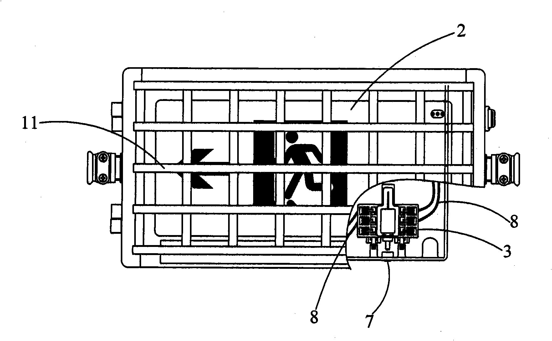
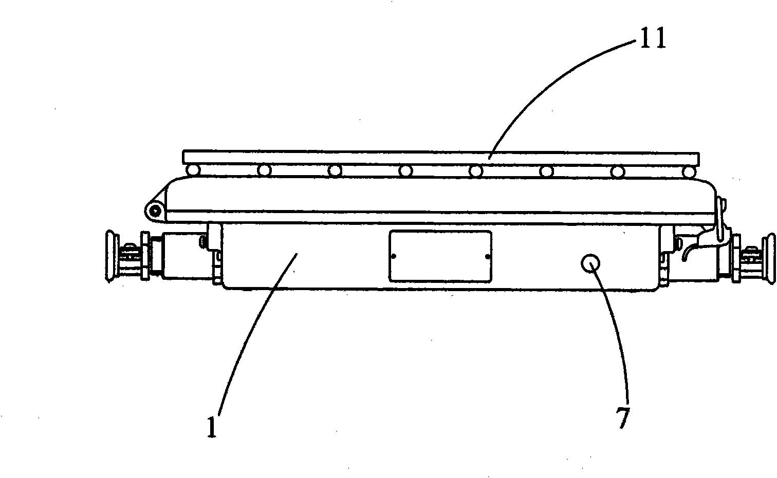
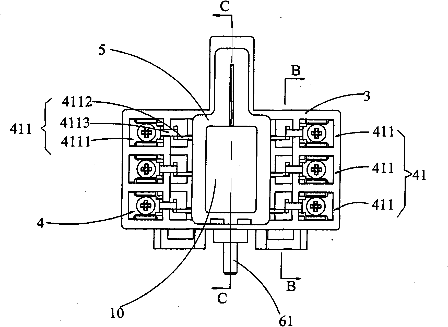
[0020] Please refer to Figure 1 to Figure 3 , is a schematic diagram of the explosion-proof marker lamp provided by the present invention. The explosion-proof sign lamp includes a lamp body 1 and a light-emitting screen assembly 2 fixed on one side of the lamp body 1. A switch box 3 is arranged in the lamp body 1, and a switch box 3 is provided in the switch box 3 to drive and light the The power supply circuit 4 of the light-emitting screen assembly 2, the switch box 3 is encapsulated by potting glue 5, a switching part 6 is also provided in the switch box 3, an...


PUM


Abstract

The invention discloses an anti-explosion marker lamp. The anti-explosion marker lamp comprises a lamp body and a light-emitting screen component fixed on one side of the lamp body, wherein a switch box is arranged in the lamp body; a power supply circuit for driving to light the light-emitting screen component is arranged in the switch box; the switch box adopts encapsulating package; a switching part is also arranged in the switch box; the lamp body is provided with a button which can drive the switching part; when the button is pressed, the switching part switches off the power supply circuit; and when the button is released, the switching part switches on the power supply circuit. In the anti-explosion marker lamp, the switch box adopts the encapsulating package and a sealing effect is good, so the interior of the anti-explosion marker lamp meets a safety-increased requirement and a safety-increased structure has the characteristics of easy manufacturing and lower cost compared with an anti-explosion structure with high difficult in the prior art. Simultaneously, the switching part which can perform emergency test on the anti-explosion marker lamp is arranged in the switch boxon the premise of meeting the safety-increased requirement, so as to prevent sparkle generated when testing from fleeing outwards and bring convenience to the test of the anti-explosion marker lamp; therefore, the anti-explosion marker lamp can be used more safely and reliably.

Description

technical field [0001] The present invention relates to a lamp, more specifically, relates to an explosion-proof sign lamp. Background technique [0002] Explosion-proof sign lights are widely used in petroleum exploration, chemical industry, military industry, ships and other dangerous environments or places. They are used for safety exit indication or as a safety evacuation guidance indication in case of power failure emergency. Existing explosion-proof sign lamps are generally internally divided into units for flameproof packaging, and the units are connected through sealed pipes and the outside is double-protected by shell sealing. The shell must meet the requirements of increased safety, that is, it must bear a certain pressure, so the production requirements for the shell are high. At the same time, due to the structure of the light-emitting screen of the explosion-proof sign lamp, it is also difficult to manufacture this kind of flameproof cavity, which increases pro...

Claims


Application Information

Patent Timeline
IPC IPC(8): F21S8/00F21V25/12F21V23/04F21V23/06G09F13/22F21W131/402
Inventor 周明杰朱建平
Owner OCEANS KING LIGHTING SCI&TECH CO LTD
Learn More