Armature coil of rotating electric machine

A technology for armature windings and rotating electrical machines, applied in the shape/pattern/structure of winding conductors, and the shape/pattern/structure of winding insulation, etc., can solve problems such as unbalanced electromagnetic force, increase terminal voltage, transmission or setting restrictions, etc. , to achieve the effects of suppressing corona discharge, improving reliability, and reducing potential difference

Active Publication Date: 2013-04-10
KK TOSHIBA
View PDF10 Cites 0 Cited by
  • Summary
  • Abstract
  • Description
  • Claims
  • Application Information

AI Technical Summary

Problems solved by technology

[0063] In addition, although it is considered that the coils are designed to be larger in order to increase the distance between the coil pieces at the ends of the coils, it leads to the need to increase the size of the rotating electrical machine, and it is difficult to transport due to the need to use too much material or increase the weight. or limited by settings
In addition, although the method of deforming the coil end after assembly to increase the coil pitch distance is also considered as a countermeasure, it becomes a problem related to the reliability of the rotating electrical machine, such as insulation damage or unbalanced electromagnetic force when the coil is deformed.
[0064] In order to increase the capacity of rotating electrical machines, it is necessary to increase the line current or terminal voltage, but for line current, it is necessary to increase the terminal voltage due to the temperature rise of the coil conductor or the limitation of size and weight.

Method used


Image

  • Armature coil of rotating electric machine
  • Armature coil of rotating electric machine
  • Armature coil of rotating electric machine

Examples


no. 1 Embodiment approach

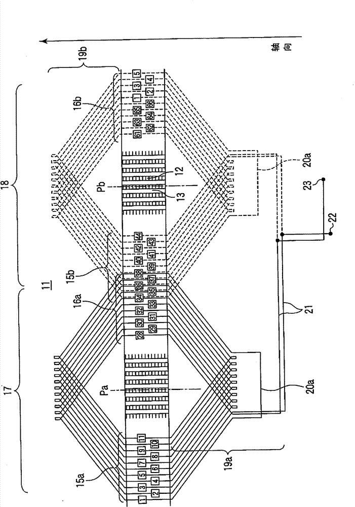
[0116] figure 1 It is an expanded schematic view showing a phase portion of the first embodiment of the armature winding of the rotating electric machine according to the present invention, figure 2 is an expanded pattern diagram of the 3-phase part of the same embodiment, for figure 1 The structure of the armature winding of the 1-phase portion shown is shown by adding 2 phases arranged so that the electrical angles are shifted by 120 degrees and 240 degrees, respectively.

[0117] Such as figure 1 As shown, the armature 11 of the rotating electrical machine is provided with 66 slots 13 on the armature core 12 composed of laminated iron cores, and the armature windings 14 of the 2-pole, 3-phase, 2-parallel circuit are accommodated in two layers in these slots. . The armature winding 14 of each phase has: an upper coil piece 15 (15a, 15b) accommodated in the opening side of the slot; a lower coil piece 16 (16a, 16b) accommodated in the bottom side of the slot; The ends...

no. 2 Embodiment approach

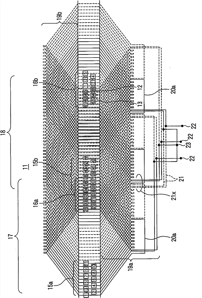
[0166] Figure 9 It is a developed schematic diagram showing the phase 1 of the second embodiment of the armature winding of the rotating electric machine according to the present invention, and the remaining two phases are constructed by shifting the electrical angles by 120 degrees and 240 degrees. related to and figure 1 The same structure, its description is omitted.

[0167] Such as Figure 9 As shown, the armature 11 of the rotating electric machine is provided with 66 slots 13 on the armature core 12 composed of laminated iron cores, and in these slots 13, the armature windings 14 of the 2-pole, 3-phase, 2-parallel circuit are accommodated in 2 layer.

[0168] In the present embodiment, the coil pitch of the coil end portion 19a on the connection side is 28, which is 1 larger than the winding pitch, and the coil pitch of the coil end portion 19b on the counter-connection side is 27, which is equal to the winding pitch.

[0169] In the second embodiment, if Figure...

no. 3 Embodiment approach

[0177] Figure 10 It is an expanded schematic view showing a 1-phase portion of a third embodiment of an armature winding of a rotating electrical machine according to the present invention, which is a 2-pole, 3-phase, 2-parallel circuit and has 66 slots in the armature core. For the remaining two phases, they are configured by shifting the electrical angle by 120 degrees and 240 degrees. related to and figure 1 The same structure, its description is omitted.

[0178] In the drawing, on the connection side, the first upper coil piece and the 28th lower coil piece are connected, and the coil pitch is 27, which is equal to the winding pitch. On the other hand, on the reverse connection side, the second upper coil piece and the 28th lower coil piece are connected, and the coil pitch is 26, which is one less than the winding pitch.

[0179] In this embodiment, if Figure 10 As shown, on the connection side coil end portion 19a of the first phase belt 17, the lead-out connecti...


PUM


Abstract

A 3-phase 2-layer armature winding of a rotating electrical machine includes upper coil pieces (15a, 15b) and lower coil pieces (16a, 16b) housed in two layers in a plurality of slots (13) provided in a armature core (12), the upper coil pieces (15a, 15b) and lower coil pieces (16a, 16b) being sequentially connected in series at a connection side coil end (19a) and a counter-connection side coil end (19b), forming one and the same phase, each phase belt of the winding having n-th parallel circuits (n is an integer larger than 1), and an output terminal lead-out connection conductor (21) connected to an output terminal (22) and a neutral terminal lead-out connection conductor (21) connected to a neutral terminal (23) being connected to the coil pieces at the connection side coil end (19a) of the each phase belt, wherein the lead-out connection conductor (21) connected to the output terminal (22) is connected to a coil piece positioned at least farther than a first coil piece inside the phase belt counted from the end of the each phase belt, and a coil piece positioned at the end of the phase belt is connected to a coil piece positioned at least farther than the n-th (n is an integer larger than 1) inside the phase belt counted from the other end of the phase belt in the same parallel circuit, by a jumper wire (20a, 20b, 20c or 20d).

Description

technical field [0001] The present invention relates to an armature winding of a rotating electrical machine capable of reducing the potential difference between adjacent coil pieces and suppressing the occurrence of corona discharge. Background technique [0002] As an armature winding of a conventional rotating electrical machine, there is a Figure 33 An armature winding of the construction shown. [0003] Figure 33 It is a sectional view showing an example of an armature winding disposed in a slot of an armature core of a rotating electric machine. [0004] exist Figure 33 Among them, 12 is an armature core formed by laminating laminated iron plates, and an armature winding 14 is housed in a slot 13 provided in the peripheral portion of the armature core 12 . [0005] The armature winding 14 is arranged in two layers of an upper coil piece 15 on the side closer to the slot opening and a lower coil piece 16 on the bottom side of the slot, and its outer periphery is cov...

Claims


Application Information

Patent Timeline
Patent Type & Authority Patents(China)
IPC IPC(8): H02K3/28H02K3/40
CPCH02K3/40H02K3/28
Inventor 藤田真史德增正垣内干雄幡野浩上田隆司长仓谦
Owner KK TOSHIBA
Why Eureka
Try Eureka