Wrapping assembly mechanism of storage battery wrapper

A technology of assembling mechanism and wrapping machine, applied in electrode manufacturing and other directions, can solve the problems of influence, poor wrapping quality, low efficiency, etc., and achieve the effect of compact overall structure, reasonable structural design, and reducing the chance of contacting the electrode plate.

Inactive Publication Date: 2010-12-08
ZHEJIANG HAIYUE AUTOMATIC MACHINERY
View PDF6 Cites 13 Cited by
  • Summary
  • Abstract
  • Description
  • Claims
  • Application Information

AI Technical Summary

Problems solved by technology

However, in the traditional "wrapping" process, manual operations are mostly used. Taking the U-shaped wrapping method as an example, the operator first takes a piece of negative plate, and wraps both sides of the positive plate with cut separator paper. The positive plate is then stacked on the negative plate to ensure that there is separator paper between each set of positive and negative plates. Repeat the above operations in a cycle to complete the plate wrapping and assembly. Not only is the efficiency low, but the quality of the wrapping is not good. High, the lead dust falling from the plate will also affect the health of the operating workers
The State Intellectual Property Office of the People's Republic of China published two patents on 2007-03-28 and 2007-09-05 respectively named "A Roller Packing Mechanism for Packing Battery Plates" and "Battery Plate Packing Machine" , although the work efficiency has been improved, there are still shortcomings. The wrapping machine provided by the two patents only completes the wrapping process of the polar plate and the separator paper, and the subsequent plate assembly process still needs to be done manually.
Therefore, compared with the traditional wrapping method, this patent only relies on the machine to automatically complete the wrapping process of the separator paper on the electrode plate, and its subsequent electrode plate assembly process has not yet got rid of the manual operation mode.

Method used


Image

  • Wrapping assembly mechanism of storage battery wrapper
  • Wrapping assembly mechanism of storage battery wrapper
  • Wrapping assembly mechanism of storage battery wrapper

Examples


Embodiment Construction

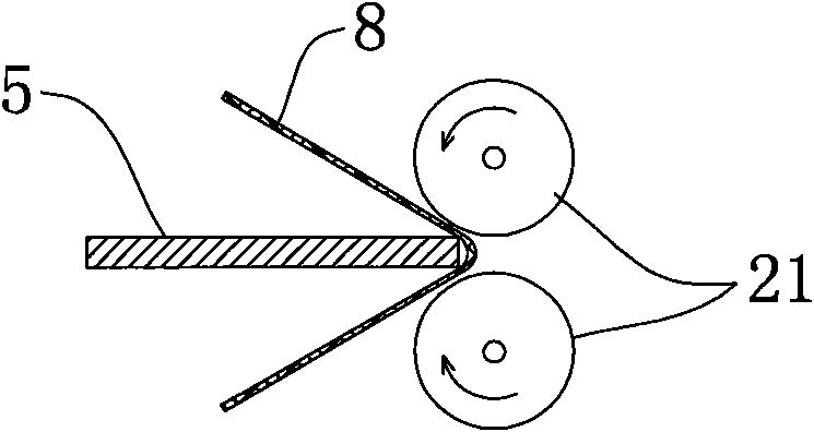
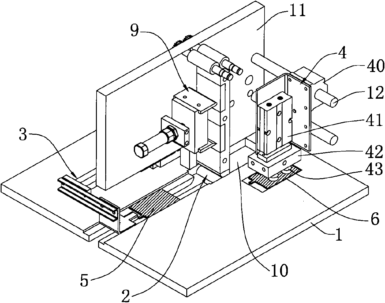
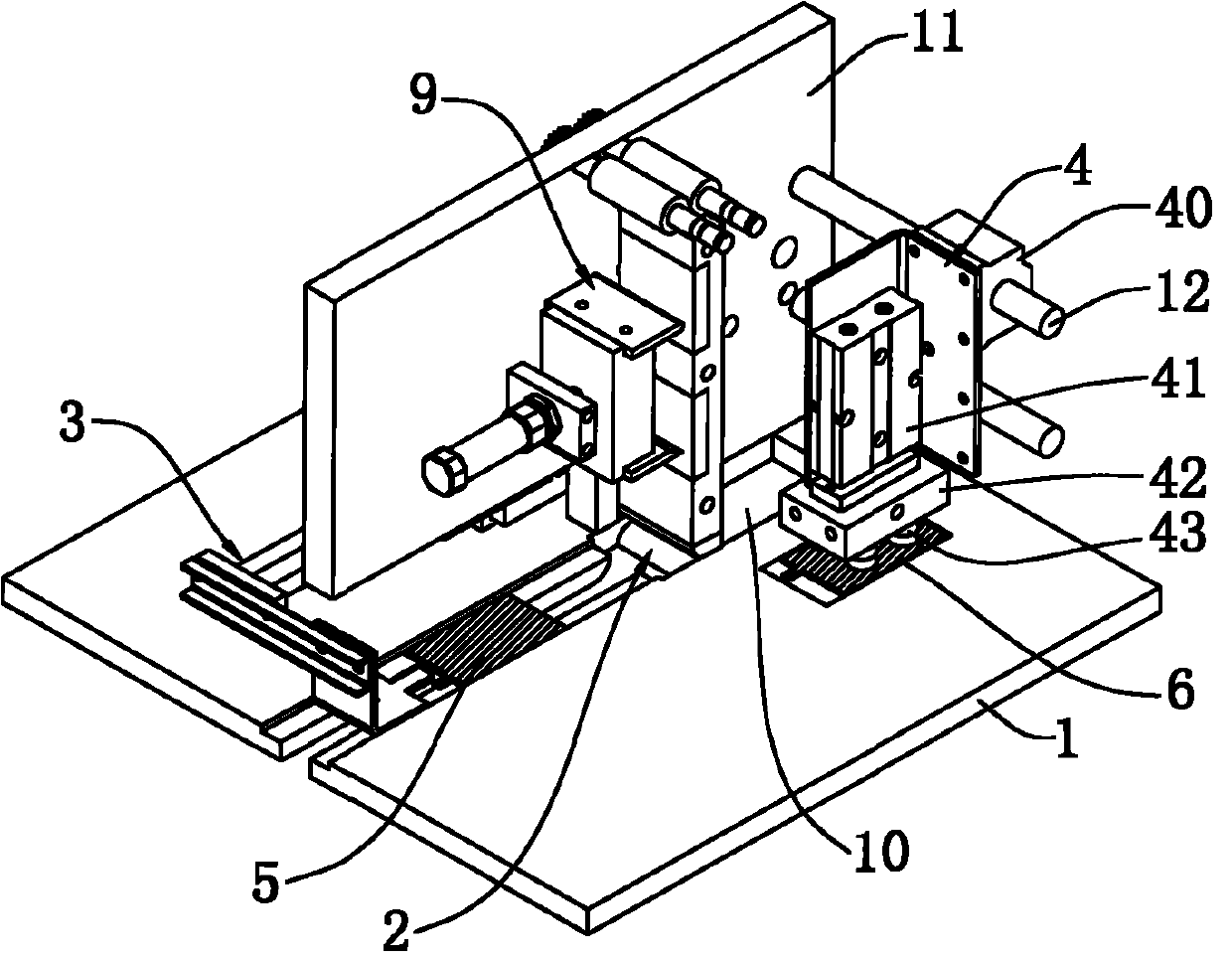
[0020] Such as Figure 1 to Figure 4 As shown, the present invention is a wrapping assembly mechanism of a battery wrapping machine, including a wrapping device for wrapping the first pole plate 5, an assembly mechanism connected to the discharge end of the wrapping device, and transporting the first pole plate to the assembly mechanism. The sheet-feeding mechanism 4 of the dipole plate 6; the sheet-wrapping device includes a sheet-wrapping part 2, a sheet-pushing mechanism 3 that pushes the first pole plate 5 to the sheet-wrapping part 2 feed openings and conveys a partition to the sheet-wrapping part 2 feed openings The paper feeding mechanism 9 of the cardboard; the assembly mechanism is an assembly box 7 connected below the outlet of the wrapping part 2, and the top of the assembly box 7 is provided with an electrode plate inlet 71.

[0021] In this embodiment, the film wrapping device, assembly mechanism and film feeding mechanism 4 are arranged in the frame assembly comp...


PUM


Abstract

The invention discloses a wrapping assembly mechanism of a storage battery wrapper, which comprises a wrapping device, an assembly mechanism and a delivering mechanism, wherein the wrapping device is used for wrapping first pole plates; the assembly mechanism is connected with the discharge end of the wrapping device; the delivering mechanism is used for delivering second pole plates to the assembly mechanism; and the wrapped first pole plates and the second pole plates are overlapped alternately in the assembly mechanism. When in work, the additional assembly mechanism and the delivering mechanism do not need manual operation, and the wrapping and assembly of the pole plates are finished in one step, thus the automation degree is greatly improved; and by reducing the chance for artificially touching the pole plates, the damage of lead dust on operators is also greatly reduced.

Description

technical field [0001] The invention relates to the technical field of storage battery manufacturing, in particular to a wrapping assembly mechanism of a storage battery wrapping machine. Background technique [0002] In the current battery production process, there is a process of assembling the positive plate, negative plate, and separator paper into an electrode group. The separator paper is sandwiched between the positive plate and the negative plate, so the industry usually calls it " In the "wrapping" or "wrapping" process, the way of wrapping is generally divided into U-type, W-type and I-type. However, in the traditional "wrapping" process, manual operations are mostly used. Taking the U-shaped wrapping method as an example, the operator first takes a piece of negative plate, and wraps both sides of the positive plate with cut separator paper. The positive plate is then stacked on the negative plate to ensure that there is separator paper between each set of positiv...

Claims


Application Information

Patent Timeline
IPC IPC(8): H01M4/04
CPCY02E60/10
Inventor 陈义忠
Owner ZHEJIANG HAIYUE AUTOMATIC MACHINERY
Why Eureka
Try Eureka