
Industrial control network redundancy fault-tolerant system

An industrial control network, redundant fault-tolerant technology, applied in the direction of comprehensive factory control, comprehensive factory control, transmission system, etc., can solve problems such as inability to solve equipment failure, opaque superstructure, and no redundant system.

Active Publication Date: 2012-07-04
DALIAN UNIV OF TECH
View PDF0 Cites 0 Cited by
  • Summary
  • Abstract
  • Description
  • Claims
  • Application Information

AI Technical Summary

Problems solved by technology

[0005] The existing ring network redundancy scheme can only solve the communication failure on the line, but cannot solve the equipment failure; the existing equipment redundancy scheme cannot solve the problems caused by the failure of the entire system due to the control network;
[0006] At the same time, the existing equipment redundancy scheme needs special host computer software to work together.
This method that requires the cooperation of the upper computer is not only complicated to operate but also opaque to the upper-level structure
For those engineers who are not very familiar with redundancy technology, this method greatly increases the complexity of deploying applications
Moreover, in the process of system application, the details of the operation of the entire redundant system need to be exposed to the upper application, which does not conform to the design concept of modularization and componentization
[0007] To sum up, there is currently no perfect redundancy system that can combine many features such as network redundancy, equipment redundancy, automatic management and hot switching.

Method used


Image

  • Industrial control network redundancy fault-tolerant system
  • Industrial control network redundancy fault-tolerant system
  • Industrial control network redundancy fault-tolerant system

Examples


Embodiment Construction

[0028] Specific embodiments of the present invention will be described in detail below in conjunction with technical solutions and accompanying drawings.

[0029] (1) Master equipment redundancy system

[0030] In the main equipment redundancy system, there are two pieces of equipment with exactly the same IP and MAC, one is the active equipment and the other is the backup equipment.

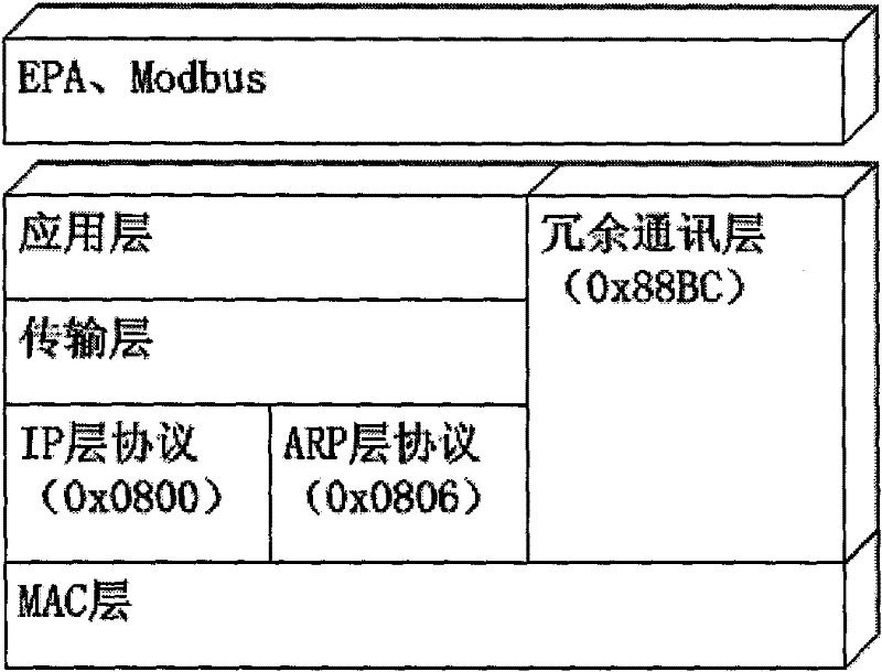
[0031] The invention designs a connection method for connecting two redundant main control devices with identical addresses to the upper-level Ethernet network through the HUB, and solves the problem caused by the device address conflict in the Ethernet. figure 1 An example is given to describe the network access mode of the main equipment redundancy system.

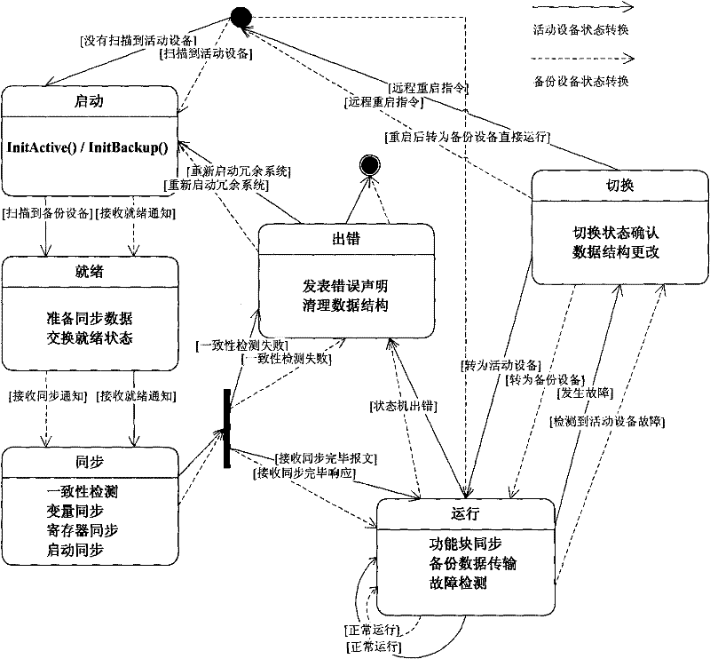
[0032] In the main control equipment redundancy system, two pieces of equipment communicate through the redundant communication layer of the present invention. In a master device redundant system, all communications between two redundant...


PUM


Abstract

The invention discloses an industrial control network redundancy fault-tolerant system, belonging to the industrial control field. The system of the invention comprises four parts, namely a main controller redundancy system, a slave redundancy system, a fault log system and a host computer monitoring interface, wherein the main controller redundancy system is composed of two main controllers which provide redundancy; each main controller carries a control network to form network redundancy or the two main controllers share one control network; the slave redundancy system is composed of a maincontroller and a pair of slaves; the main controller monitors the communication condition of the current line and selects the best communication path in real time; the fault log system records the fault message of the device; and the host computer monitoring interface provides communication response for a monitoring computer and processes input operation to control the operation of the redundancysystem. The system of the invention can ensure that the resources of the control network of the two redundancies synchronize automatically; the fault can be judged automatically; and when the networkhas a failure, the network can be switched to a backup control network within 300 milliseconds to operate continuously.

Description

technical field [0001] The invention belongs to the field of industrial control, and proposes an industrial-grade control system that integrates functions such as equipment synchronization, fault detection and self-recovery, fault reporting, and equipment hot switching in the field of industrial production that requires high reliability and high safety. Design methods for redundant fault-tolerant systems. Background technique [0002] Redundancy technology is one of the design methods for systems or equipment to obtain high reliability, high security and high survivability, and it is a very important means to achieve fault tolerance. In important industrial production fields and industries, it is more and more common to use redundant technology to improve the reliability of control systems. Conventional redundancy is to take part in the control by doubling the components in order to minimize the downtime caused by the accident of the control equipment. [0003] A redundant...

Claims


Application Information

Patent Timeline
Patent Type & Authority Patents(China)
IPC IPC(8): G05B19/418H04L1/22
CPCY02P90/02
Inventor 仲崇权董智超付树东乔国卫师文汇
Owner DALIAN UNIV OF TECH
Learn More