Supercharge Your Innovation With Domain-Expert AI Agents!

Thermal evaporation device

A technology of thermal evaporation and substrate, which is applied in vacuum evaporation plating, sputtering plating, ion implantation plating, etc. It can solve the problems of low particle kinetic energy and inability to form a coating layer, achieve high film strength and improve coating quality. The effect of high rate and strong film density

Inactive Publication Date: 2010-12-08
HONG FU JIN PRECISION IND (SHENZHEN) CO LTD +1
View PDF3 Cites 3 Cited by
  • Summary
  • Abstract
  • Description
  • Claims
  • Application Information

AI Technical Summary

Problems solved by technology

However, during the coating process, due to the low kinetic energy of the coating material particles produced by thermal evaporation, it is usually impossible to form a coating layer with high film strength and strong film density.

Method used


Image

  • Thermal evaporation device
  • Thermal evaporation device
  • Thermal evaporation device

Examples


Embodiment Construction

[0008] The embodiments of the present invention will be further described in detail below in conjunction with the accompanying drawings.

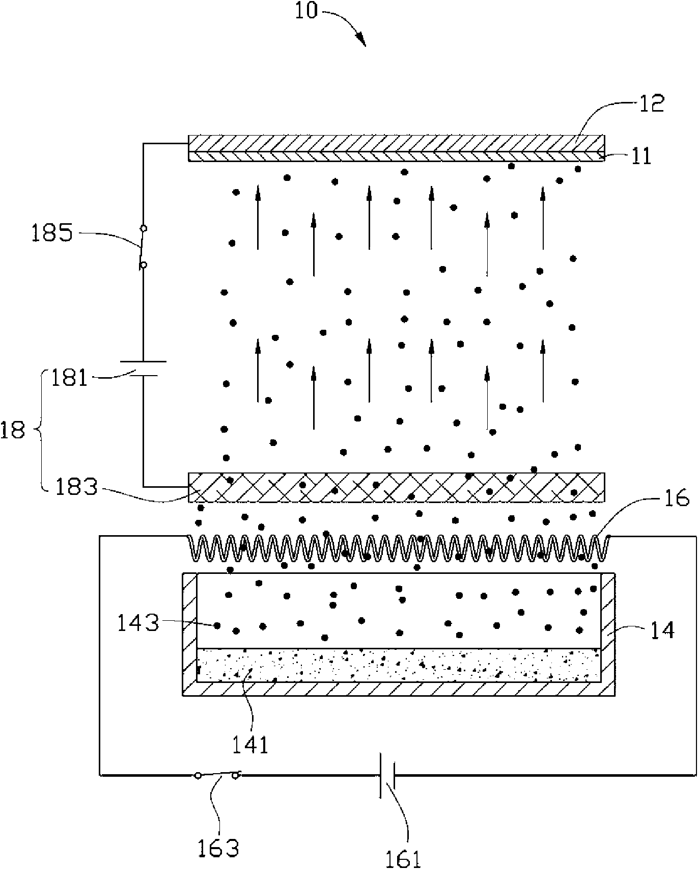
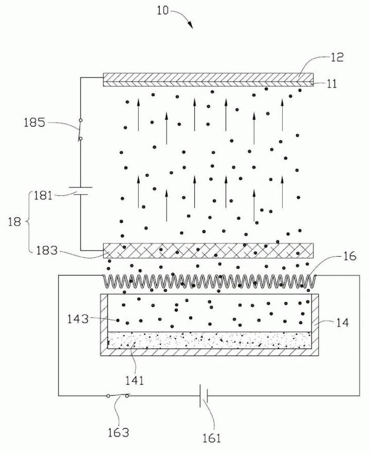
[0009] see figure 1 , the thermal evaporation device 10 provided in the first embodiment of the present invention is used to coat a substrate 11 to be coated. The thermal evaporation device 10 includes a substrate base 12 , a crucible 14 , a tungsten wire 16 and an electric field generating component 18 . The substrate base 12 is used to carry the substrate to be coated 11 . The crucible 14 is disposed relative to the substrate base 12 for carrying the evaporation material 141 . The tungsten wire 16 is located between the substrate to be coated 11 and the crucible 14 . The electric field generating component 18 is used for generating an electric field applied between the substrate base 12 and the crucible 14 .

[0010] In this embodiment, the substrate to be coated 11 is made of non-metallic material, and the substrate base 12 is made o...


PUM


Abstract

The invention relates to a thermal evaporation device which comprises a substrate base used for bearing a substrate to be coated with a film, a crucible which is arranged opposite to the substrate base and used for bearing an evaporation material, a tungsten wire arranged between the substrate to be coated with a film and the crucible and an electric field generation assembly, wherein the tungsten wire is electrically connected with a first external power supply to ensure that electrons are generated on the surface of the tungsten wire; the electric field generation assembly is used for generating an electric field applied between the substrate base and the crucible; and evaporation material molecular gas generated by heating by the crucible carries the electrons through the tungsten wire to ensure that the evaporation material molecular gas carrying the electrons is accelerated to reach the substrate to be coated with a film. The thermal evaporation device ensures that the film strength of a film formed on the substrate to be coated with a film is higher and the film layer compactness is stronger through increasing the kinetic energy of the evaporation material molecular gas so as to improve the film coating yield of the substrate to be coated with a film.

Description

technical field [0001] The invention relates to a coating device, in particular to a thermal evaporation device. Background technique [0002] The equipment used in thermal evaporation coating technology is low in cost and simple in technology, and is widely used in various fields. However, during the coating process, due to the low kinetic energy of the coating material particles produced by thermal evaporation, it is usually impossible to form a coating layer with high film strength and strong film density. Contents of the invention [0003] In view of this, it is necessary to provide a thermal evaporation device capable of forming a coating layer with higher film strength and stronger film density. [0004] A thermal evaporation device, which includes a substrate base for carrying a substrate to be coated, a crucible arranged opposite to the substrate base and used to carry evaporation materials, and a crucible located between the substrate to be coated and the crucibl...

Claims


Application Information

Patent Timeline
IPC IPC(8): C23C14/24
Inventor 蔡泰生
Owner HONG FU JIN PRECISION IND (SHENZHEN) CO LTD
Features
  • R&D
  • Intellectual Property
  • Life Sciences
  • Materials
  • Tech Scout
  • Unparalleled Data Quality
  • Higher Quality Content
  • 60% Fewer Hallucinations
Learn More