
Drive method and drive circuit of liquid crystal display device

A technology of a liquid crystal display device and a driving method, which can be applied to static indicators, instruments, etc., can solve problems such as uneven color and crosstalk, and achieve the effects of reducing production costs, reducing power consumption, and improving image display effects.

Inactive Publication Date: 2010-12-01
SHANGHAI TIANMA MICRO ELECTRONICS CO LTD
View PDF1 Cites 19 Cited by
  • Summary
  • Abstract
  • Description
  • Claims
  • Application Information

AI Technical Summary

Problems solved by technology

[0011] The purpose of the present invention is to provide a driving method of a liquid crystal display device and its driving circuit, which can solve the problems of visually uneven color and crosstalk caused by the polarity inversion method in the prior art

Method used


Image

  • Drive method and drive circuit of liquid crystal display device
  • Drive method and drive circuit of liquid crystal display device
  • Drive method and drive circuit of liquid crystal display device

Examples


Embodiment Construction

[0037] The inventors of the present invention have found that in the existing polarity inversion technology applied to thin film transistor liquid crystal display devices, especially for frame inversion and line inversion, due to the interference between adjacent pixel units is easy to occur Crosstalk affects the display effect of images.

[0038] The inventors also found that in the dot inversion technology with better image display effect, since the common voltage signal on the common electrode used is a direct current voltage, in order to ensure that the applied data signal voltage and the common voltage signal are applied on the liquid crystal layer The voltage difference can exceed a certain predetermined value, so that the voltage amplitude difference between the high-level value and the low-level value of the applied data signal is quite large, resulting in a considerable power consumption during dot inversion.

[0039] In view of this, the present invention provides a ...


PUM


Abstract

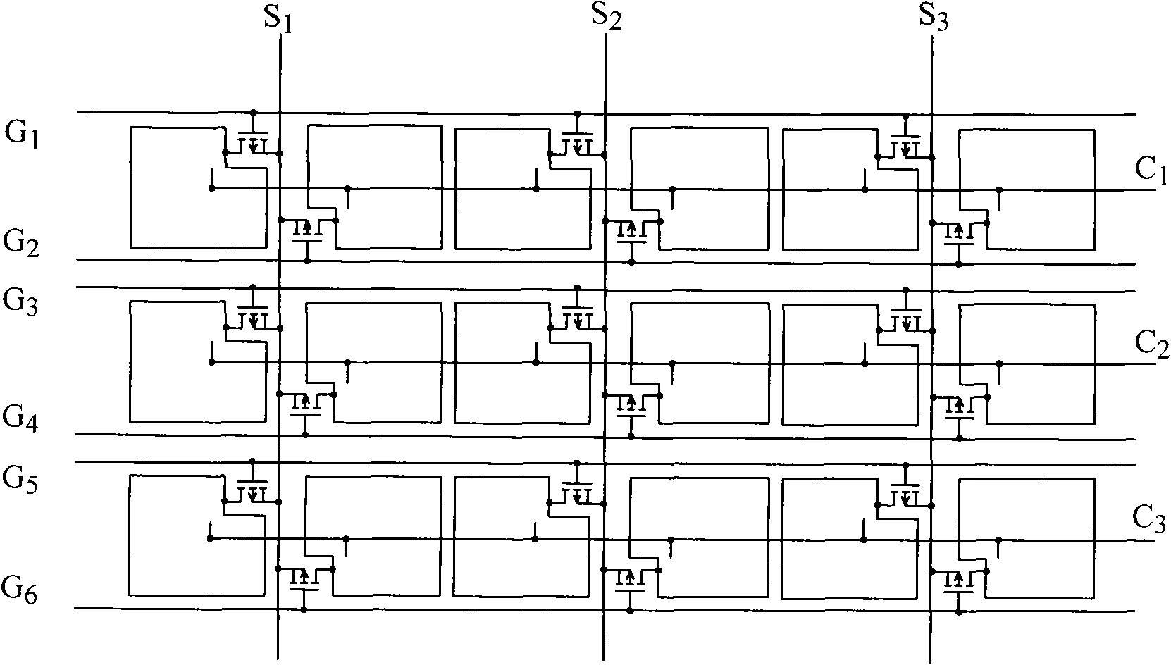
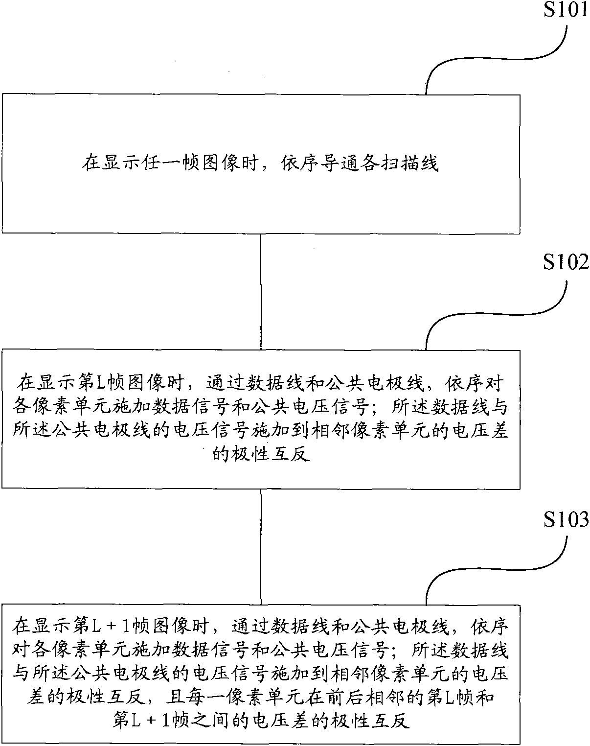
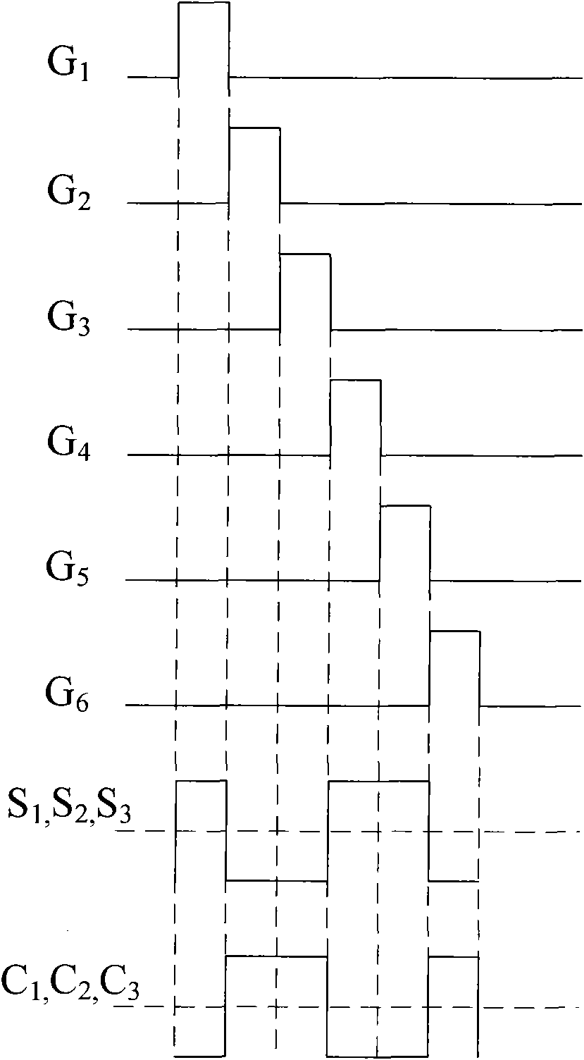
The invention relates to a drive method and drive circuit of a liquid crystal display device. The liquid crystal device comprises a plurality of pixel units, scanning lines, data lines and common electrode wires, wherein each two scanning lines are connected with one row of pixel units; each two lines of pixel units commonly use one data line; each row of common electrode wires is connected with one row of pixel units. The drive method comprises the following steps: when a frame of image is displayed, all the scanning lines are conducted in sequence; and voltage signals are applied on the pixel units through the data lines and the common electrode wires; and the voltage differences of the voltage signals, applied on the adjacent pixel unit, of the data lines and the common electrode wires have opposite polarities so as to execute dot inversion. By using the drive method of the invention, the voltage differences of the data voltage and common voltage applied on the pixel units show different polarities so as to realize dot inversion; and the AC square-wave voltage signal is adopted as the common voltage signal, thus relatively reduce power consumption.

Description

technical field [0001] The invention relates to liquid crystal display technology, in particular to a driving method of a liquid crystal display device and a driving circuit thereof. Background technique [0002] Due to the advantages of lightness, thinness, small footprint, low power consumption, and low radiation, liquid crystal display devices are widely used in various data processing equipment, such as televisions, notebook computers, mobile phones, and personal digital assistants. With the continuous development of the electronic industry, the performance of liquid crystal display devices is getting higher and higher. [0003] Taking a common thin film transistor liquid crystal display (Thin Film Transistor Liquid Crystal Display, TFT-LCD) as an example, it is a kind of active matrix liquid crystal display. The main feature of TFT-LCD is that each pixel is equipped with a semiconductor switching device, and each pixel is an independent transistor isolated from each ot...

Claims


Application Information

Patent Timeline
Patent Type & Authority Applications(China)
IPC IPC(8): G09G3/36G02F1/133
Inventor 李元
Owner SHANGHAI TIANMA MICRO ELECTRONICS CO LTD
Learn More