
Ware mould clamp of glassware

A technology for glassware and utensils, applied in glass forming, glass pressing, glass manufacturing equipment and other directions, can solve the problems of damage to the bottom surface of the half mold of the fixture, reduced opening and closing effect, affecting the forming efficiency, etc., to speed up cooling, improve The effect of forming efficiency and improving heat dissipation effect

Active Publication Date: 2012-02-29
CHANGSHU JIANHUA MOLD TECH
View PDF0 Cites 53 Cited by
  • Summary
  • Abstract
  • Description
  • Claims
  • Application Information

AI Technical Summary

Problems solved by technology

[0003] The above clamp half-molds have the following deficiencies in the actual use process: first, the service life is short and the scrapping frequency is high, because a pair of clamp half-molds are opened and closed once every time a glassware is pressed, that is, every time a glassware is formed, so, The bottom surface of the fixture half-mold and the surface of the base mold frequently rub against each other, causing both to be damaged, and must be replaced in time; second, the stagnation phenomenon is serious, and even damages the surface of the base and the bottom surface of the fixture half-mold, because during the pressing and forming process of the glassware , the flash at the seam of the glass product is easy to fall to the surface of the base, so when the mold half of the fixture is opened and closed, the cooled and solidified glass particles will enter between the bottom surface of the mold half of the fixture and the surface of the base, thus damaging the half of the fixture. The bottom surface of the mold and the surface of the base are damaged; the third is that the cooling speed of the jig half mold is slow, which affects the improvement of forming efficiency, which in turn affects the output per unit time; the fourth is the pivot shaft used to set the pivot shaft on the pivot shaft The service life of the seat is short, because the pivoting shaft seat also rubs frequently during the opening and closing process of the jig halves. Whole waste
[0004] Therefore, how to reasonably extend the service life of the container mold fixture has become a common concern of glassware manufacturers and glass mold manufacturers and a technical problem that needs to be solved urgently. The applicant, as a professional production unit of glass molds, has also carried out Long-term attention, and also conducted a literature search, but there is no enlightenment aimed at solving the above problems in the published patent and non-patent literature

Method used


Image

  • Ware mould clamp of glassware
  • Ware mould clamp of glassware
  • Ware mould clamp of glassware

Examples


Embodiment Construction

[0023] In order to enable the examiners of the patent office, especially the public, to understand the technical essence and beneficial effects of the present invention more clearly, the applicant will describe in detail below in conjunction with the accompanying drawings in the form of embodiments, but none of the descriptions of the embodiments is a description of the present invention. Restriction of the inventive solution, any equivalent transformation made according to the concept of the present invention which is only in form but not in substance shall be regarded as the scope of the technical solution of the present invention.

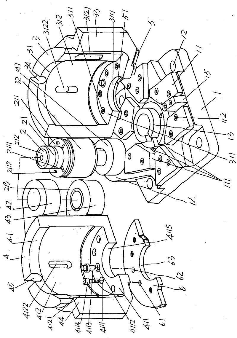
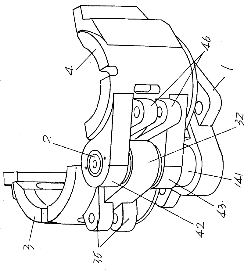
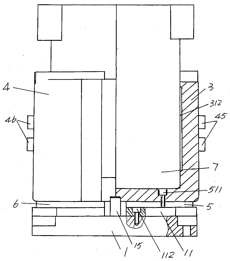
[0024] Please see figure 1 and figure 2 , the shape of the base 1 given is generally a cube, and the general concept used here means that the base 1 can be either a cube or a cuboid. Each of the four corners of the base 1 is provided with a fixing bolt hole 12, the fixing bolt hole 12 is used for fixing with the glass container processing mach...


PUM


Abstract

The invention relates to a ware mould clamp of glassware, which belongs to a glass mould and comprises a pedestal, a pivoted shaft, a first clamp semi-mould and a second clamp semi-mould. The ware mould clamp is characterized in that a group of pedestal inlaid pieces are arranged on the surface of the pedestal towards the first clamp semi-mould and the second clamp semi-mould, a first semi-mould inlaid piece is arranged on the surface of the bottom wall of a first ware semi-mould cavity towards one side of the pedestal, a second semi-mould inlaid piece is arranged on the surface of the bottomwall of a second ware semi-mould cavity towards one side of the pedestal, and both the first semi-mould inlaid piece and the second semi-mould inlaid piece are matched with the pedestal inlaid pieces. The invention has the advantages that the service life of the pedestal, the first clamp semi-mould and the second clamp semi-mould is prolonged; the ware mould clamp is convenient to clear; the forming efficiency is improved; and a first pivoted shaft seat, a second pivoted shaft seat and a third pivoted shaft seat are protected.

Description

technical field [0001] The invention belongs to the technical field of glass moulds, and in particular relates to a glassware mold fixture. Background technique [0002] As known to those skilled in the art, in the process of manufacturing (pressing) glassware such as glasses (including glasses with handles and glasses without handles), stirrer vessels, glass jugs, etc., due to the The mold is a two-opening structure, that is, a double-opening mold structure, so it cannot be directly installed on the machine. It must be installed on the glass container processing machine by the vessel mold fixture as the vessel mold carrier and a pair of vessel half molds. The structure of the utensil mold fixture is composed of a base and a pair of clamp halves with the same shape that are coaxially pivoted (also called hinged) on the base. The container half-mold is detachably arranged on a pair of jig half-molds, and the opening and closing of the pair of clamp half-molds drives the pair...

Claims


Application Information

Patent Timeline
Patent Type & Authority Patents(China)
IPC IPC(8): C03B11/06C03B11/10
CPCC03B11/10
Inventor 马建华晏庆宝
Owner CHANGSHU JIANHUA MOLD TECH
Learn More