System and method for internal cooling of a fuel injector

A technology of fuel injectors and injectors, which is applied in fuel injection devices, charging systems, machines/engines, etc., and can solve problems such as increasing fuel temperature, increasing deposit rate by temperature, and increasing temperature of injected fuel

Active Publication Date: 2010-11-17
CATERPILLAR INC
View PDF6 Cites 5 Cited by
  • Summary
  • Abstract
  • Description
  • Claims
  • Application Information

AI Technical Summary

Problems solved by technology

One disadvantage of mixing cooled fuel with injected fuel is the resulting temperature rise of the injected fuel
For example, heat removed from the piezoelectric actuator of the device disclosed in the '101 p

Method used


Image

  • System and method for internal cooling of a fuel injector
  • System and method for internal cooling of a fuel injector
  • System and method for internal cooling of a fuel injector

Examples


Embodiment Construction

[0018] The systems and methods described herein are used to cool internal components and systems of a fuel injector of an internal combustion engine. This cooling allows the fuel injector to operate at increased injection pressures and further reduces the deposition of debris on internal components of the fuel injector.

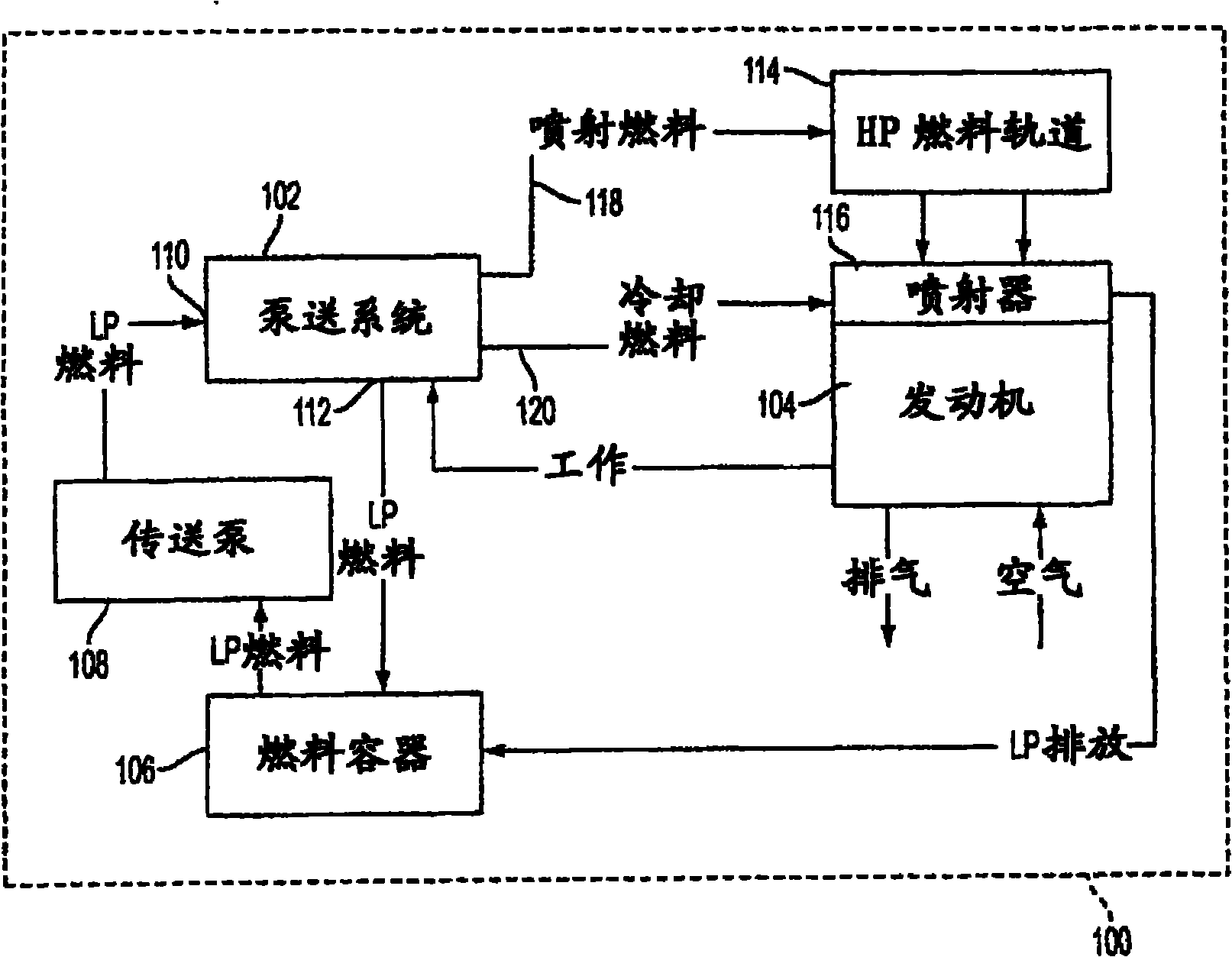
[0019] figure 1 A block diagram of an engine system 100 is shown having a high pressure (HP) fuel pumping system 102 operatively associated therewith. The engine system 100 includes an internal combustion engine 104 connected to the pumping system 102 . Engine 104 may be a compression ignition or diesel engine that mixes air and fuel in multiple combustion chambers during operation. Fuel at low pressure (LP) is supplied to pumping system 102 from a fuel tank or container 106 . A transfer or low pressure pump 108 is provided adjacent to the fuel container to pump fuel from the fuel container 106 and to supply fuel at low pressure to the pumping system 102 t...


PUM


Abstract

A fuel injector includes an injector body forming an actuator portion. An actuator bore is formed in the actuator portion and is at least partially defined by an inner surface and by an end surface. An actuator disposed in the actuator bore and has an outer surface such that a flow channel can be defined between the inner surface of the actuator bore and the outer surface of the actuator. A cooling flow passage is formed in the injector body, in fluid communication with the actuator bore, and is adapted to supply cooling fluid to the actuator bore. A drain passage is formed in the injector body, in fluid communication with the actuator bore. An internal cooling fluid flow path extends from the cooling flow passage, through the flow channel, and from the flow channel through the drain passage.

Description

technical field [0001] The present invention relates generally to fuel injectors and, more particularly, to cooling arrangements for fuel injectors associated with internal combustion engines. Background technique [0002] Internal combustion engines having fuel injectors associated with each cylinder are well known. Typical fuel injectors are located under the engine's valve cover and are in direct fluid communication with the cylinders. Fuel injectors include various valves and valve arrangements that inject fuel into cylinders in a controlled manner. These valves are typically controlled by electronic actuators associated with each fuel injector. Each fuel injector is capable of injecting a quantity of fuel into a cylinder of the internal combustion engine at a predetermined time and for a predetermined duration. During operation, the valves that inject fuel into the cylinders are controlled by electrical signals sent to the electronic actuators. [0003] Modern engin...

Claims


Application Information

Patent Timeline
IPC IPC(8): F02M53/04
CPCF02M47/027F02M53/043
Inventor D·R·伊布拉西姆S·R·刘易斯A·R·马努伯鲁
Owner CATERPILLAR INC
Why Eureka
Try Eureka