
Apparatus and method for controlling fan drive in computer system

a technology of computer system and fan drive, applied in the direction of electric controller, motor/generator/converter stopper, dynamo-electric converter control, etc., can solve the problems of more expensive installation, control and management of hardware based on the 8-bit resolution than the one based on the 4-bit resolution

Inactive Publication Date: 2007-03-13
LG ELECTRONICS INC
View PDF33 Cites 17 Cited by
  • Summary
  • Abstract
  • Description
  • Claims
  • Application Information

AI Technical Summary

Benefits of technology

The present invention provides an apparatus and method for controlling a device in a computer system that can output a plurality of control signals and combine them to control the device. This allows for more complex control signals to be output and combined to achieve better control of the device. The invention also provides an apparatus and method for controlling a fan drive in a computer system that can output a plurality of pulse width modulation control signals and vary their rotation speed to reduce power consumption and decrease the internal temperature of the computer system. The invention also provides an apparatus and method for controlling a fan drive in a computer system that can output a plurality of pulse width modulation control signals based on a higher resolution than the first resolution. Overall, the invention allows for more precise and complex control of the device in a computer system.

Problems solved by technology

In this case, the cooling fan 182 is unnecessarily rotated by an additional “100” RPM, and hence power is wasted.
Further, as the cooling fan 182 is unnecessarily rotated, noise can be incurred.
However, the hardware based upon the 8-bit resolution is more expensive to install, control and manage than that based upon the 4-bit resolution.
Where the hardware based upon the 8-bit resolution is used, there are problems in that a size of the hardware is increased and that it is difficult for the computer system to be simplified.

Method used


Image

  • Apparatus and method for controlling fan drive in computer system
  • Apparatus and method for controlling fan drive in computer system
  • Apparatus and method for controlling fan drive in computer system

Examples


Embodiment Construction

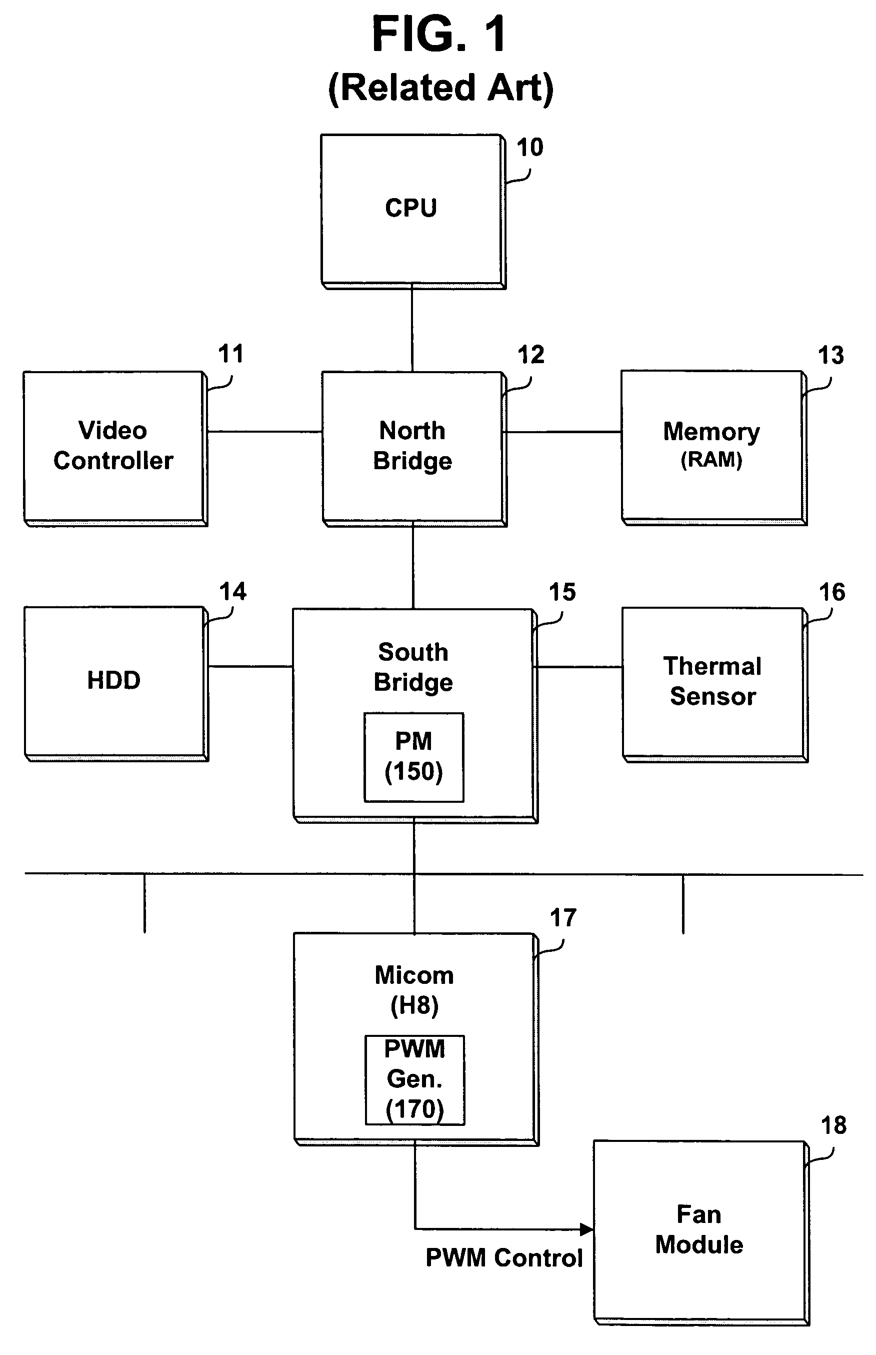
[0035]Embodiments of apparatus and methods for controlling the fan drive can be applied to various computer systems such as a notebook computer, a personal computer, etc. The embodiments of apparatus and methods for controlling fan speed in accordance with the present invention can be applied to portable computers configured by the components of FIG. 1 and will be described using the components shown in the computer system of FIG. 1. For example, a microcomputer 17 embedded in a computer system can be constituted by hardware (H / W) of a pulse width modulation (PWM) control signal generator 170 and software (S / W) of a PWM controller 171 as shown in FIG. 4. However, the present invention is not intended to be so limited.

[0036]As shown in FIG. 4, the hardware of the PWM control signal generator 170 can generate PWM control signals (e.g., PWM PATTERNS 0˜15 at 16 STEPS 0˜15) of N-bit resolution, for example, the 4-bit resolution described with reference to FIG. 3. The software of the PWM ...


PUM


Abstract

Embodiments of an apparatus and method can control a fan drive in a computer system. Such embodiments of apparatus and methods can alternately output a plurality of pulse width modulation (PWM) control signals at a predetermined time ratio and variably control a rotation speed of a cooling fan. The embodiments can use simple hardware based upon N-bit resolution in a PWM control signal generator included in the computer system for controlling the rotation speed of the cooling fan decreasing an internal temperature, such that the rotation speed of the cooling fan can be precisely and variably controlled, equally with the effect of an operation for controlling the fan drive using hardware based upon resolution of more than the N bits. Further, a physical configuration can be effectively simplified, and unnecessary power consumption can be reduced or prevented.

Description

BACKGROUND OF THE INVENTION[0001]1. Field of the Invention[0002]The present invention relates to an apparatus and method for controlling a fan drive in various computer systems such as a notebook computer, a personal computer and etc[0003]2. Background of the Related Art[0004]FIG. 1 is a block diagram illustrating the configuration of a conventional computer system. Various computer systems such as a notebook computer, a personal computer and etc. include a central processing unit (CPU) 10, a video controller 11, a north bridge 12, a random access memory (RAM) 13, a hard disk drive (HDD) 14, a south bridge 15, a thermal sensor 16, a microcomputer 17, a cooling fan module 18, etc.[0005]Further, the south bridge 15 is equipped with a power manager (PM) 150 for managing system power. The microcomputer 17 is equipped with a pulse width modulation (PWM) control signal generator 170 for variably controlling a rotation speed of a cooling fan.[0006]The thermal sensor 16 detects an internal ...

Claims


Application Information

Patent Timeline
Patent Type & Authority Patents(United States)
IPC IPC(8): G05B11/28G06F1/20H05K7/20
CPCG06F1/206H05K7/20209Y02B60/1275Y02D10/00G06F1/20
Inventor HA, CHANG JIN
Owner LG ELECTRONICS INC
Learn More