
Adjustable portal frame template supporting system

A formwork support and portal frame technology, applied in the preparation of pillars and building components on site, construction, etc., to achieve the effects of enhanced adaptability, enhanced application, and simple construction operations

Inactive Publication Date: 2010-11-17
QINGDAO XINHUAYOU CONSTR GROUP
View PDF2 Cites 4 Cited by
  • Summary
  • Abstract
  • Description
  • Claims
  • Application Information

AI Technical Summary

Problems solved by technology

[0003] Aiming at the deficiencies of the prior art, the technical problem to be solved by the present invention is to provide a width-adjustable gantry formwork support system to solve the supporting application of the gantry when the structural space changes greatly or the upper load is too large problems, in order to reduce construction difficulty and cost expenditure, and improve engineering efficiency

Method used


Image

  • Adjustable portal frame template supporting system
  • Adjustable portal frame template supporting system
  • Adjustable portal frame template supporting system

Examples


Embodiment 1

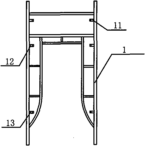
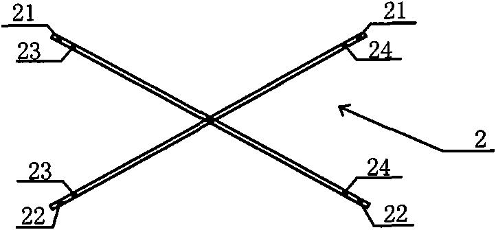
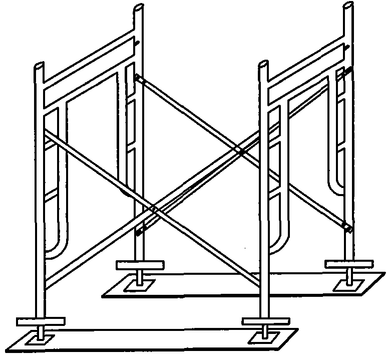
[0020] The present invention is an adjustable gantry formwork support system, which includes a number of gantry frames 1 arranged in parallel. The sides of two adjacent gantry frames are provided with cross supports 2. The vertical rods of the gantry frames are Three lock pins are vertically arranged on the top respectively; two limit holes are respectively set at both ends of the cross-supported support rod, and the limit holes are matched with the lock pins. The distance between the lock pin 11 on the top of the pole and the top of the portal frame 1 is 300 millimeters, the distance between the bottom lock pin 13 and the bottom end of the portal frame 1 is 600 millimeters, and the distance between the middle lock pin 12 and the top of the portal frame 1 is 700 millimeters. The distance between the two limiting holes 21 and 22 at the outer end of the support rod 2 is 1700 mm, and the distance between the two limiting holes 23 and 24 at the inner end is 1500 mm. The present in...

Embodiment 2

[0024] The difference between this embodiment and Embodiment 1 is that the two limiting holes at the inner end of the support rod are respectively connected with the middle lock pin and the bottom lock pin on the vertical rod, and the combined width of the portal frame thus formed is 900 mm.

Embodiment 3

[0026] The difference between this embodiment and Embodiment 1 is that the two limiting holes at the outer end of the support rod are respectively connected with the upper locking pin and the lower locking pin on the vertical rod, and the combined width of the portal frame thus formed is 570 mm.


PUM


Abstract

The invention discloses an adjustable portal frame template supporting system. The adjustable portal frame template supporting system comprises a plurality of portal frames which are arranged in parallel, wherein a crossed support is arranged on the sides of two adjacent portal frames respectively; at least two lock pins with the same number are longitudinally arranged on an upright rod of each portal frame; at least one limit hole is formed at the two ends of a supporting rod of the crossed support respectively; and the limit holes are matched with the lock pins. The number of the lock pins and the crossed supporting limit holes is increased, so the combination modes of the portal frames are increased; the adaptability to the load change of complicated-dimension structural space or member is enhanced; the application of the portal frames in a structure template supporting system is obviously enhanced on the premise of meeting the safety requirement; the problem of insufficient applicability of the conventional portal frames due to fixed width is solved; the construction operation is simple; and the project benefit is effectively improved.

Description

technical field [0001] The invention relates to a portal frame support system, in particular to an adjustable portal frame formwork support system, which belongs to the construction field. Background technique [0002] The traditional portal frame formwork support system relies on the combination of standard components to form a support system with a certain combined width. When the width modulus is too large and does not meet the above-mentioned width modulus, it cannot be adjusted flexibly, and the practicability is very insufficient. In the formwork support of beam members, if the beam load is too large and the portal frame formwork support system with fixed combined width cannot meet the bearing capacity requirements, another type of portal frame and its accessories will have to be replaced, which will increase the cost Expenditure, and increase the difficulty of engineering organization. Contents of the invention [0003] Aiming at the deficiencies of the prior art,...

Claims


Application Information

Patent Timeline
Patent Type & Authority Applications(China)
IPC IPC(8): E04G25/02
Inventor 杨建新
Owner QINGDAO XINHUAYOU CONSTR GROUP
Learn More