
Computer graphics method for manufacturing centrifugal rating plate

A drawing method and computer technology, applied in calculation, special data processing applications, instruments, etc., to achieve the effect of reducing drawing time and improving work efficiency

Inactive Publication Date: 2010-11-10
JIANGSU KEDA HUIFENG SCI & TECH
View PDF3 Cites 5 Cited by
  • Summary
  • Abstract
  • Description
  • Claims
  • Application Information

AI Technical Summary

Problems solved by technology

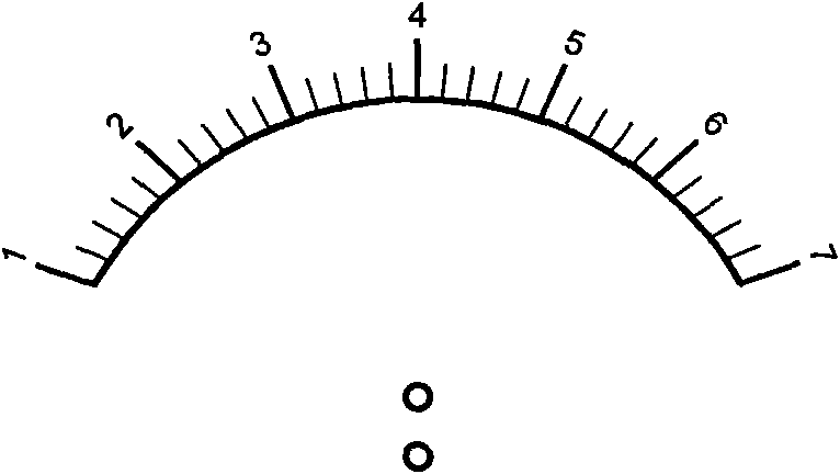
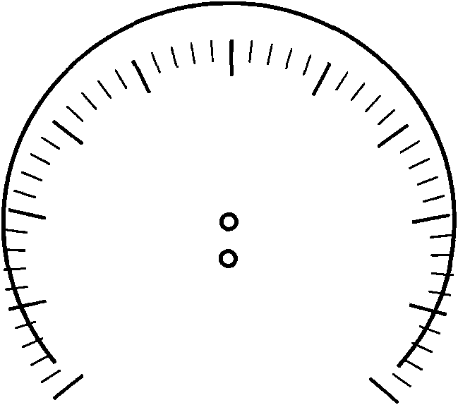
The starting angle and ending angle of the outer centrifugal scale arc are not theoretically 0 to 180 degrees. According to the upper and lower positions of the center of the scale line at the center of the arc, the arc length may be less than 180 degrees (such as Figure 4 ), it may also be an arc length greater than 180 degrees (such as Figure 5 ), the 0-degree scale line in the scale line is only a theoretical deflection of 0 degrees, and the actual deflection angle relative to the center of the arc is not zero

Method used


Image

  • Computer graphics method for manufacturing centrifugal rating plate
  • Computer graphics method for manufacturing centrifugal rating plate
  • Computer graphics method for manufacturing centrifugal rating plate

Examples


Embodiment Construction

[0030] The present invention will be further described below in conjunction with drawings and embodiments.

[0031] The sign making system is generally composed of a drawing computer and a laser phototypesetter. The computer and the phototypesetter are interconnected for communication. The computer converts the drawn sign graphic file into a file format compatible with the laser phototypesetter and outputs it to the phototypesetter. The phototypesetter prints out the film production afterwards. The present invention utilizes ObjectARX2008 to carry out secondary development for AutoCAD2008, such as Figure 6 As shown, the centrifugal sign making computer graphics method includes the following steps:

[0032] 1) input arc parameters, including the radius of the arc, the center coordinates, the starting and ending angles, the center coordinates of the scale marks; in the present embodiment, the arc center coordinates are (0,0), the radius is 30mm, and the starting point The ang...


PUM


Abstract

The invention discloses a computer graphics method for manufacturing centrifugal rating plate, comprising the following steps: inputting a circular arc parameter, and graphing an auxiliary circle; according to the circular arc start angle parameter, drawing an auxiliary radial and intersecting with the auxiliary circle, and calculating the practical start angle of the circular arc according to the intersection; obtaining the practical end angle of the circular arc with the same method, and graphing a main circular arc according to the obtained practical start and end angle; deleting the auxiliary radial and the auxiliary circle; according to one of three scale angle deflection methods, calculating to obtain the theoretical deflection angle of each scale mark on the circular arc; drawing the auxiliary circle taking the circle center of the circular arc as the center and the radius of the scale mark as the radius; according to the theoretical deflection angle parameter of each scale mark, graphing an auxiliary radial of which the starting point is the circle center of the scale mark, and obtaining the intersection of the auxiliary radial and the auxiliary circle, i.e. the practical starting point of the scale mark; the scale mark is successively graphed according to the parameters such as, the practical starting point, the theoretical deflection angle, the length and the like ofthe scale mark.

Description

technical field [0001] The invention relates to a graphic drawing method, in particular to a computer drawing method for centrifugal sign making, which belongs to the technical field of printing. Background technique [0002] With the popularity of computers in factories, more and more companies use CAD software for drawing. In the sign making process of sign factories, CAD drawing software is generally used to draw and save the sign graphics that need to be produced in the computer. Then convert the sign graphic file into a file format compatible with the laser imagesetter and output it to the imagesetter, and the imagesetter prints out the film for production. At present, some improvements have been made to the sign drawing method in the existing technology. Based on the AutoCAD drawing software, the sign is drawn by inputting the parameters of the sign arc, scale line, and scale value, which improves the work efficiency. But for some special signs, such as torque meter s...

Claims


Application Information

Patent Timeline
IPC IPC(8): G06F17/50
Inventor 薛峰于萧榕
Owner JIANGSU KEDA HUIFENG SCI & TECH
Learn More