Eureka AIR delivers breakthrough ideas for toughest innovation challenges, trusted by R&D personnel around the world.

Optical fiber connector

An optical fiber connector and optical fiber technology, which is applied in the coupling of optical waveguides and other directions, can solve the problems of long time curing, time-consuming production, and many assembly process steps.

Active Publication Date: 2010-11-10
SHENZHEN EPLU SCI TECH
View PDF3 Cites 17 Cited by
  • Summary
  • Abstract
  • Description
  • Claims
  • Application Information

AI Technical Summary

Problems solved by technology

The common structure of an optical fiber is composed of a core, a coating layer, a tight sleeve layer, a spun layer, and a protective jacket from the inside to the outside. After the glue is cured, the final assembly of the shell is carried out. The existing structure has many assembly process steps, and the production is time-consuming
When dispensing glue on the end of the optical fiber, the ceramic ferrule and the ceramic ferrule seat, it takes a long time for the glue to solidify at room temperature, usually about 50 minutes to 1 hour. In addition, when the optical fiber connector is small in size To a certain extent, the assembly of optical fiber connectors with existing structures is difficult. In view of this, how to improve the structure and assembly process of existing optical fiber connectors to improve production efficiency and facilitate assembly has become a technical problem to be solved.

Method used


Image

  • Optical fiber connector
  • Optical fiber connector
  • Optical fiber connector

Examples


Embodiment Construction

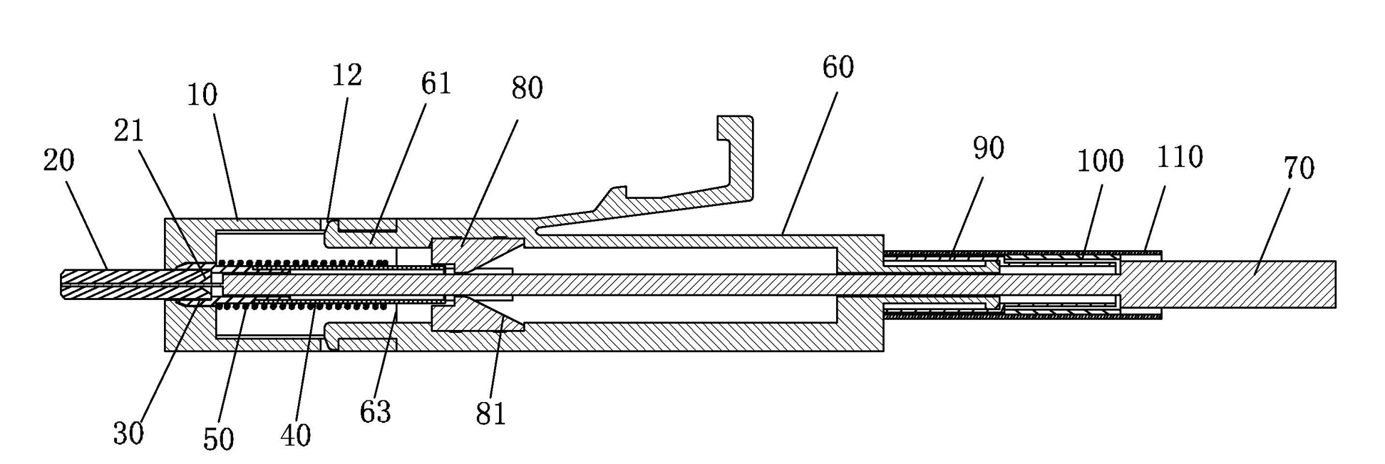
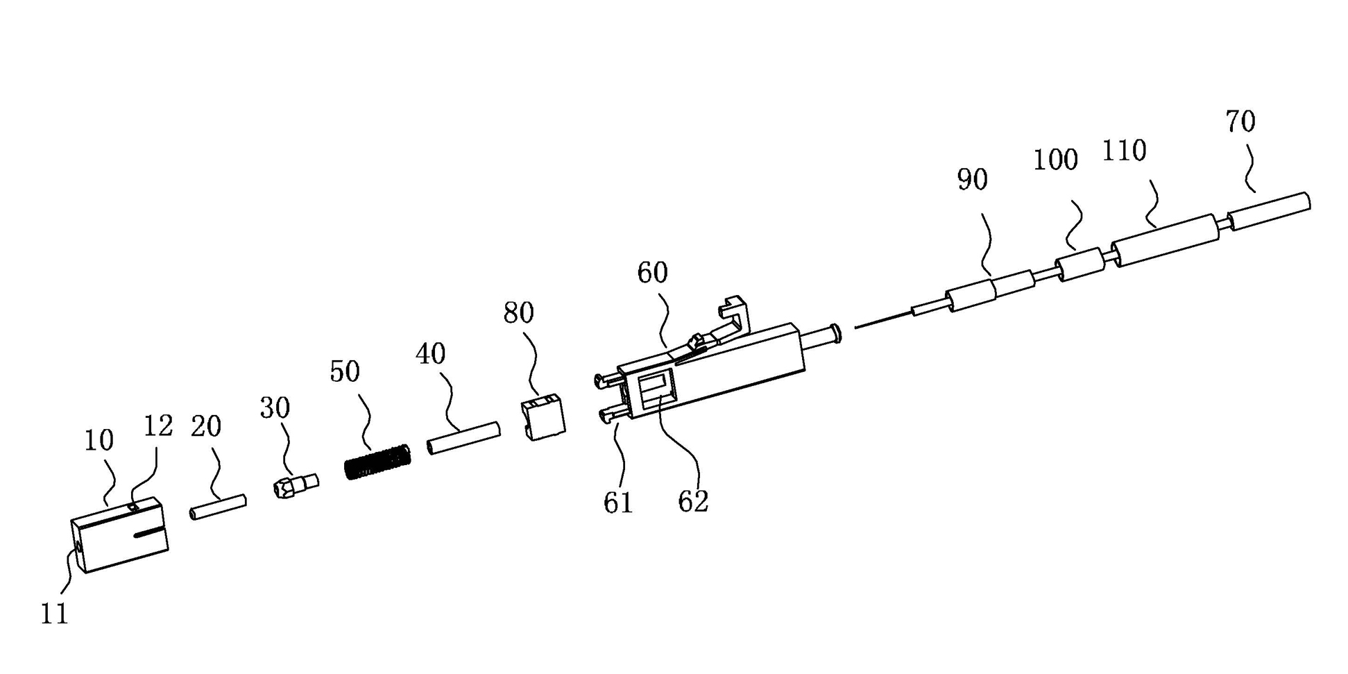
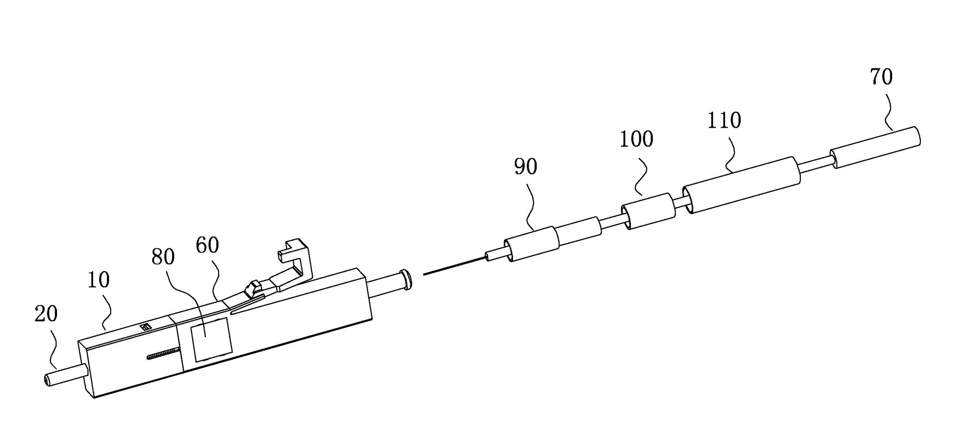
[0015] Figure 1-4 As shown, the optical fiber connector of the present invention includes: a ceramic ferrule housing 10, a ceramic ferrule 20, a spring 50, and a housing body 60; when assembling, a fixing glue is dropped into the core hole of the ceramic ferrule 20, After the ceramic ferrule housing 10 and the housing body 60 are snap-connected to each other, after the processed optical fiber 70 passes through the housing body 60 in turn, the core of the front end of the optical fiber 70 is inserted into the core hole in the ceramic ferrule 20 Inside.

[0016] Such as Figure 1-3 In the first embodiment of the optical fiber connector shown, a cavity is opened inside the ceramic ferrule housing 10, the rear end of the ceramic ferrule housing 10 is opened, and the front end of the ceramic ferrule housing 10 is opened for the ceramic ferrule 20 to pass through. Set the through hole 11; one end of the ceramic ferrule 20 is inserted and fixed to the front port of the ceramic ferrule ...


PUM


Abstract

The invention relates to the technical field of optical fiber connectors, in particular to an optical fiber connector. The optical fiber connector comprises a ceramic ferrule shell, a ceramic ferrule, a spring and a shell body; in the process of assembly, fixing glue is dripped in the hole of the ceramic ferrule, the ceramic ferrule shell is fastened with the shell body, a processed optical fiber then sequentially runs through the shell body, and finally, the fiber core of the front end of the optical fiber is inserted in the hole in the ceramic ferrule. After the structure is adopted, the structure and the assembling method of the optical fiber connector optimize the conventional assembling steps, save the assembling time, and increase the production efficiency, so that assembly becomes simpler.

Description

Technical field [0001] The invention relates to the technical field of optical fiber connection devices, in particular to an optical fiber connector. Background technique [0002] With the development of network technology, optical fiber has been increasingly used as a high-speed, broadband data communication connection device. The commonly used structure of optical fiber is composed of inner to outer core, coating layer, tight sleeve layer, spun fiber layer, and protective outer covering in turn. The existing assembly structure of optical fiber connector is mostly first dispense and insert the optical fiber. The final assembly of the shell is carried out after the glue is cured. The existing structure has many assembly process steps, and the production is relatively time-consuming. When dispensing the fiber end, ceramic ferrule and ceramic ferrule seat, the glue takes a long time to cure at room temperature, usually about 50 minutes to 1 hour. In addition, when the optical fibe...

Claims


Application Information

Patent Timeline
IPC IPC(8): G02B6/38
Inventor 王七月夏志刚杨国
Owner SHENZHEN EPLU SCI TECH
Why Eureka
Eureka Blog
Learn More