Intelligent electric power parameter tester
An intelligent power and tester technology, applied in multi-tester circuits and other directions, can solve the problems of single function of measuring instruments, complex field wiring structure, inconvenient maintenance and management, etc., and achieve the effects of high measurement accuracy, high cost performance and high sensitivity
Inactive Publication Date: 2010-11-10
HUAZHONG UNIV OF SCI & TECH
View PDF2 Cites 16 Cited by
- Summary
- Abstract
- Description
- Claims
- Application Information
AI Technical Summary
Problems solved by technology
[0002] In order to ensure the safe operation of the power grid, it is necessary to monitor various operating parameters of the power grid in real time, and to send various measurement parameters to the dispatching monitoring cent
Method used
View moreImage
Smart ImageViewing Examples
Examples
 PUM
 Abstract
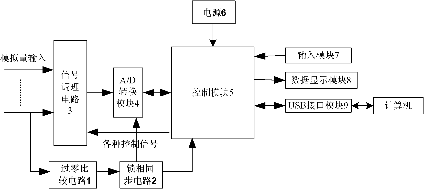
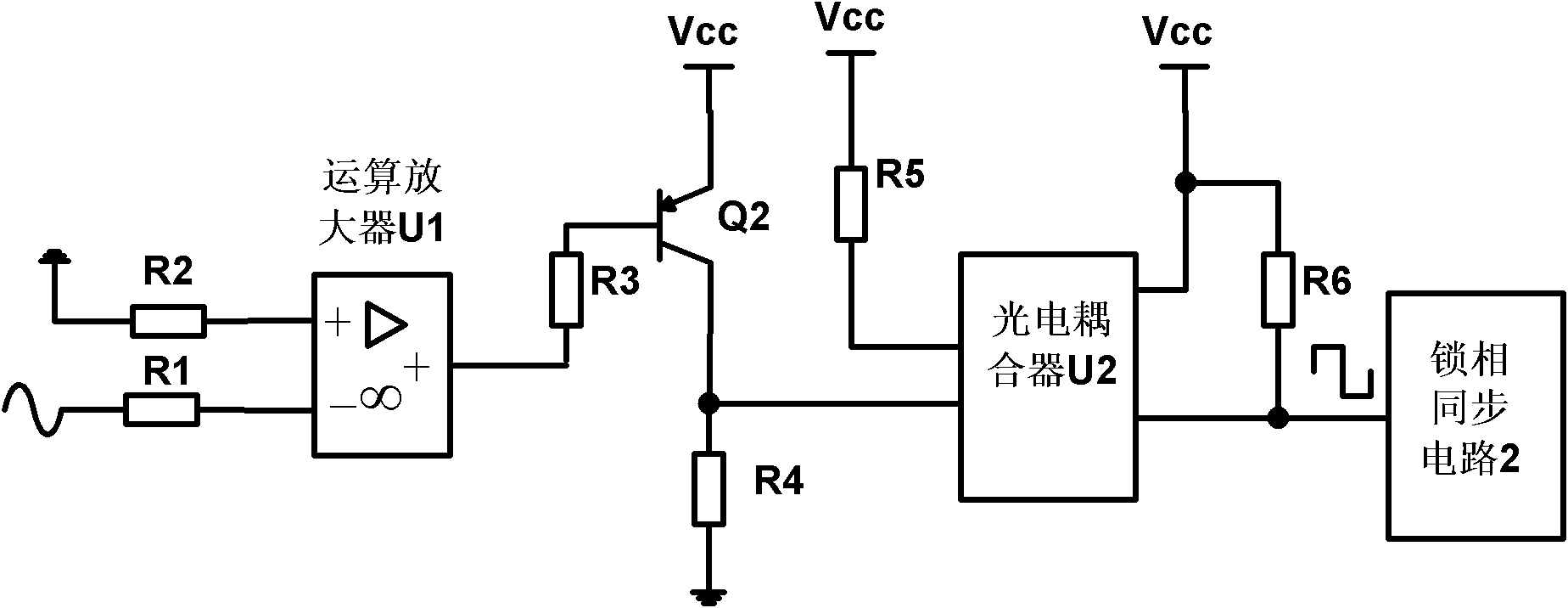
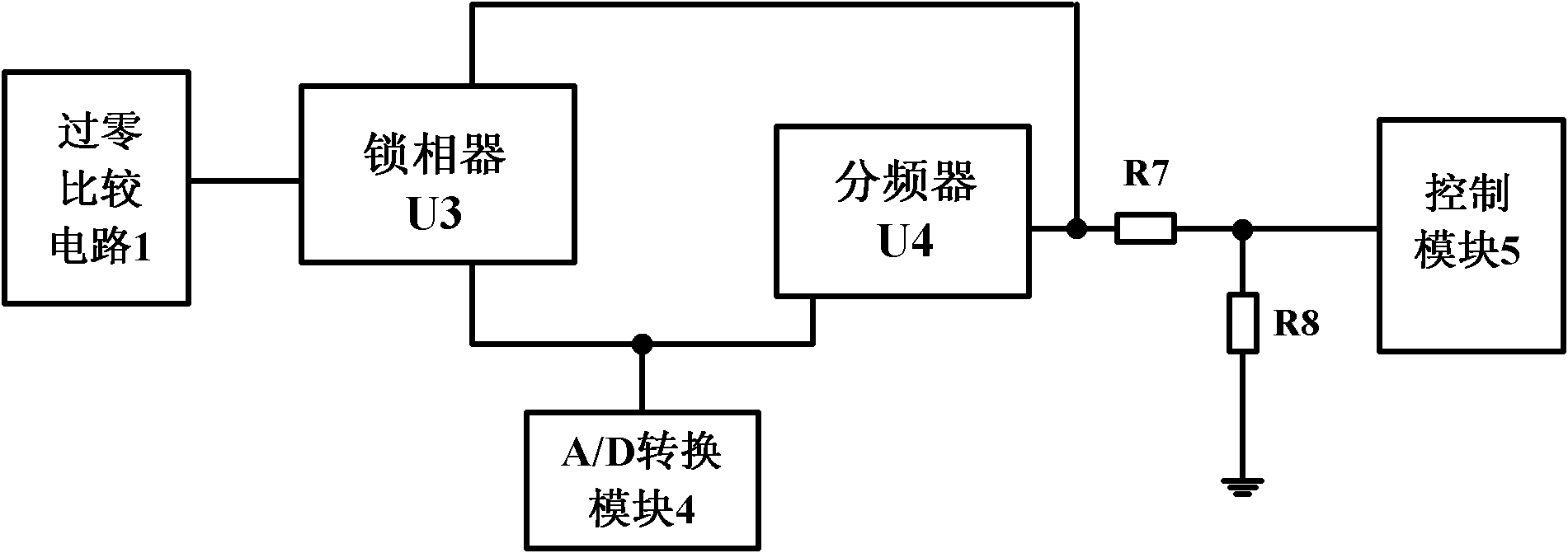
The invention discloses an intelligent electric power parameter tester, which comprises a zero-crossing comparison circuit, a phase locking synchronous circuit, a signal conditioning circuit, an A/D conversion module, a control module, a power supply, an input module, a data display module and a USB interface module. Multiple electric power parameters are measured by adopting a DSP digital processing chip, and the intelligent electric power parameter tester has the unique advantages in aspects of improvement on measurement accuracy, real-time digital signal processing and intellectualization. In the intelligent electric power parameter tester, voltage and current at the same phase are respectively used as a real part and an imaginary part of a complex sequence to perform Fourier transform, and the intelligent electric power parameter tester has the maximal advantage that various electric power parameters (voltage effective values, current effective values, frequency, harmonic waves, power factors, active power, reactive power and the like) in a power grid can be solved simultaneously by only one-time the Fourier transform of the complex sequence, so the calculated amount is reduced, and the real-time and accuracy of measurement are improved. The intelligent electric power parameter tester can be widely applied in occasions such as electric power departments, industrial and mining enterprises and the like where the multiple parameters of an electric power system are needed to be measured automatically.
Description
technical field [0001] The invention belongs to the technical field of power system measurement, and in particular relates to an intelligent power parameter tester based on DSP control. Background technique [0002] In order to ensure the safe operation of the power grid, it is necessary to monitor various operating parameters of the power grid in real time, and to send various measurement parameters to the dispatching monitoring center in a timely manner as required. However, in practical applications, there are often single-function measuring instruments, so that This results in complex on-site wiring structures, inconvenient maintenance and management, and high costs. Contents of the invention [0003] The purpose of the present invention is to overcome the above disadvantages and provide an intelligent power parameter tester, which has simple structure, reliable performance, low cost, and has the functions of automatic range conversion and communication with computers,...
Claims
Login to View More Application Information
Patent Timeline
 IPC IPC(8): G01R15/12
Inventor 魏伟
Owner HUAZHONG UNIV OF SCI & TECH
Features
- Generate Ideas
- Intellectual Property
- Life Sciences
- Materials
- Tech Scout
- Unparalleled Data Quality
- Higher Quality Content
- 60% Fewer Hallucinations
Learn More Browse by: Latest US Patents, China's latest patents, Technical Efficacy Thesaurus, Application Domain, Technology Topic, Popular Technical Reports.
© 2025 PatSnap. All rights reserved.Legal|Privacy policy|Modern Slavery Act Transparency Statement|Sitemap|About US| Contact US: help@patsnap.com


