
Primary measurement shell for measurement while-drilling instrument

A technology of measurement while drilling and instruments, which is applied in the directions of measurement, earthwork drilling, borehole/well components, etc., and can solve problems such as inability to operate the measurement subsystem, difficulty in installation and disassembly, and failure to adopt circumferential layout structure design, etc.

Inactive Publication Date: 2010-11-10
DAQING PETROLEUM ADMINISTRATION
View PDF7 Cites 4 Cited by
  • Summary
  • Abstract
  • Description
  • Claims
  • Application Information

AI Technical Summary

Problems solved by technology

At present, the parameter measurement point of the measurement while drilling instrument is far from the bottom of the well; the maintenance, repair and battery replacement of each measurement subsystem cannot be performed on site
The main reason for this phenomenon is that the main measuring shell has the following disadvantages: 1. The main measuring shell is long. If it is installed below the bending point of the motor, it will inevitably increase the length of the transmission shaft and increase the fracture or breakage of the transmission shaft. Therefore, it must be installed above the bending point of the motor, causing the measuring point to be far from the bottom of the well; The shell space is equivalent to being connected in series, and the measuring points cannot be close to the bottom of the well at the same time, resulting in a distance between the measuring point and the bottom of the well; Only the main measuring shell can open the instrument compartment, and there are connectors inside the main measuring shell, and the main measuring shell needs to be disassembled by using dismantling racks and other equipment. It is difficult to install and disassemble, so the measurement subsystem cannot be operated on site

Method used


Image

  • Primary measurement shell for measurement while-drilling instrument
  • Primary measurement shell for measurement while-drilling instrument
  • Primary measurement shell for measurement while-drilling instrument

Examples


Embodiment Construction

[0019] Below in conjunction with accompanying drawing, the present invention will be further described:

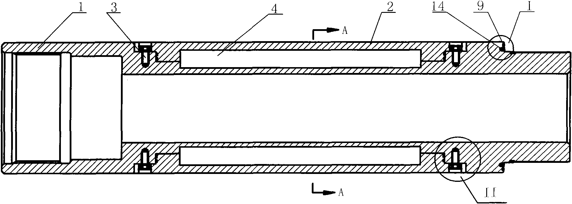
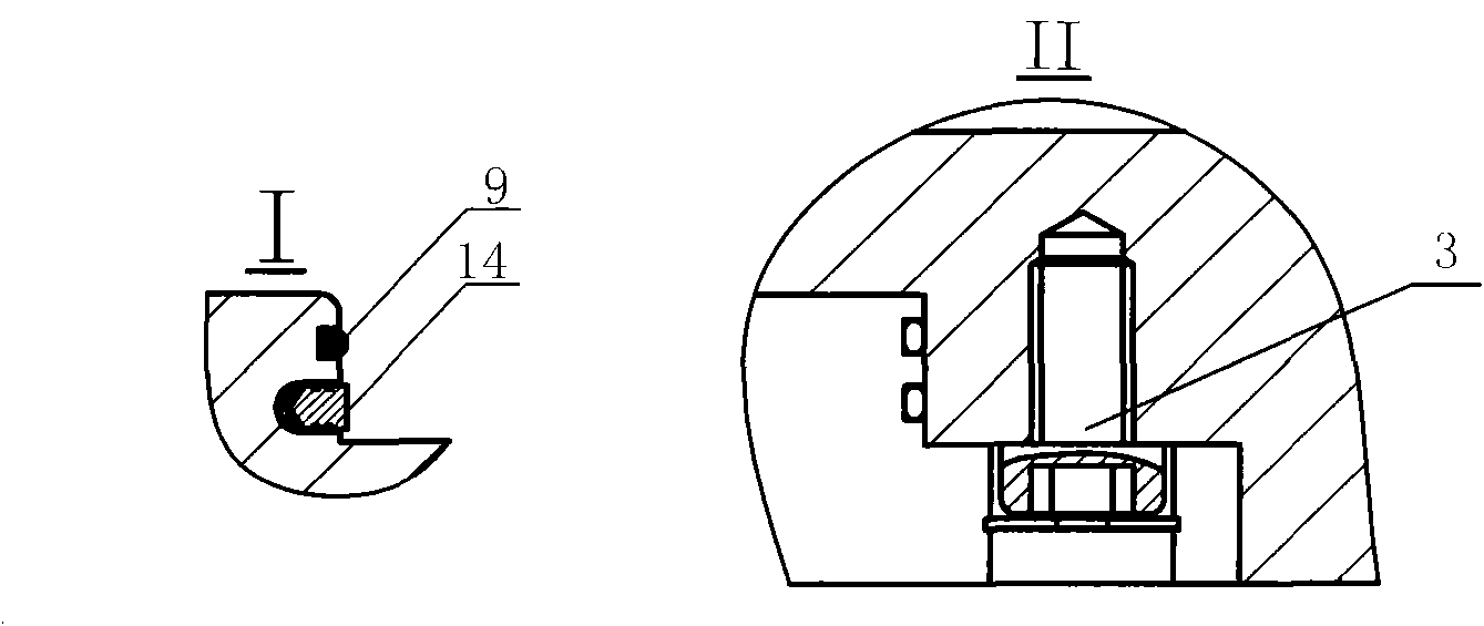
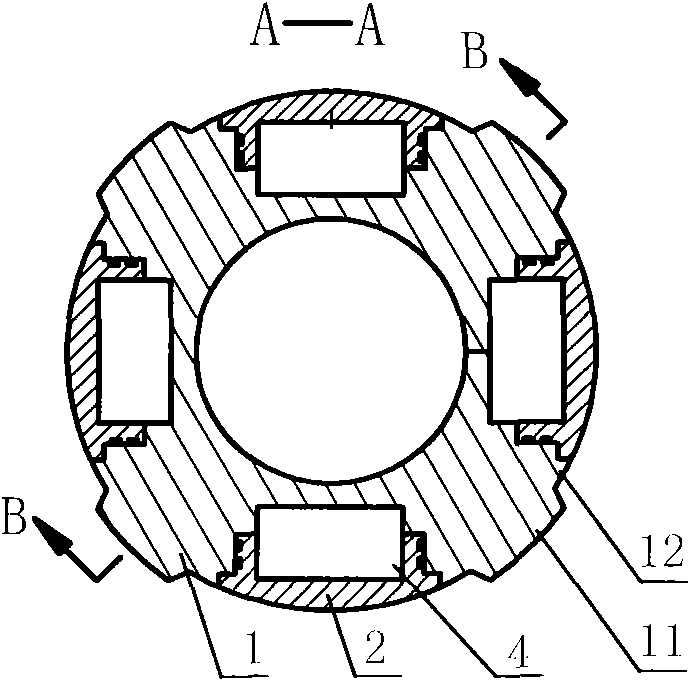
[0020] Depend on figure 1 to combine figure 2 , image 3 As shown, the main measuring housing used for the measuring instrument while drilling includes a short joint body 1, a buckle cover 2, and a conductive ring 14; wherein the short joint body 1 is evenly milled with alternating convex walls 11 along the circumferential direction, and the convex wall 11 Quantity is identical with the quantity of the instrument of measuring while drilling to be placed, preferably 4, forms recessed wall 12 between convex wall 11, is milled with stepped groove on recessed wall 12, and the structure of buckle cover 2 is corresponding to the structure of stepped groove, The buckle cover 2 is buckled on the stepped groove, and fixed with fastening screws and snap rings 3. The joint of the buckle cover 2 and the sub body 1 is prefabricated with an instrument cabin 4, which can be in various...


PUM


Abstract

The invention relates to a primary measurement shell for a measurement while-drilling instrument. The primary measurement shell comprises a short joint body, a buckling cover and a conductive ring; the short joint body is uniformly milled with alternated convex walls along the circumferential direction, concave walls are formed among the convex walls, step grooves are milled on the concave walls, the buckling cover is fixed on the step grooves, closed instrument compartments are preformed at the combination part of the buckling cover and the short joint body, an axial routing hole is drilled on a shoulder at a male buckle end of the short joint body, a routing through hole is drilled between the instrument compartments, a conductive ring slot is lathed on the shoulder surface at the male buckle end of the short joint body, the conductive ring is placed in the conductive ring slot, and a routing hole is drilled in the conductive ring slot; and the routing hole, the routing through hole and the axial routing hole are communicated. The primary measurement shell can perform measurement while drilling, can realize short-distance measurement of each measurement subsystem, is convenient to assemble and disassemble, and can be maintained and expanded on site.

Description

Technical field: [0001] The invention relates to an oil drilling downhole testing instrument. Background technique: [0002] The measurement-while-drilling instrument uses geological and engineering parameter measurement and control-while-drilling means to ensure that the drilled wellbore passes through the reservoir and can realize geosteering. It is an advanced drilling technology, and the design of the main measurement shell is the key to the measurement-while-drilling system One of the techniques. At present, the parameter measurement point of the measurement while drilling instrument is far away from the bottom of the well; the maintenance, repair and battery replacement of each measurement subsystem cannot be performed on site. The main reason for this phenomenon is that the main measuring shell has the following disadvantages: 1. The main measuring shell is long. If it is installed below the bending point of the motor, it will inevitably increase the length of the tr...

Claims


Application Information

Patent Timeline
Patent Type & Authority Applications(China)
IPC IPC(8): E21B47/12
Inventor 杨志坚王广新杨智光杨决算李玉海谷玉堂范存郭福祥姚萍王海淼
Owner DAQING PETROLEUM ADMINISTRATION
Learn More