
A laser ranging weight block

A technology of laser ranging and heavy blocks, which is applied in the direction of transportation, packaging, and load hanging components, can solve the problems of low safety of ranging heavy blocks and small ranging ranges, and achieve improved wireless signal strength, protection modules, The effect of expanding the measurement range

Active Publication Date: 2021-10-01
保定市汇邦电气有限公司
View PDF0 Cites 0 Cited by
  • Summary
  • Abstract
  • Description
  • Claims
  • Application Information

AI Technical Summary

Problems solved by technology

[0004] The purpose of the present invention is to provide a laser ranging weight, which can solve the problems of small ranging range and low safety of the ranging weight

Method used


Image

  • A laser ranging weight block
  • A laser ranging weight block
  • A laser ranging weight block

Examples


specific Embodiment

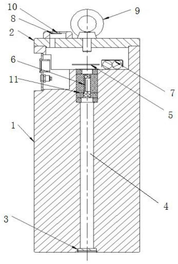
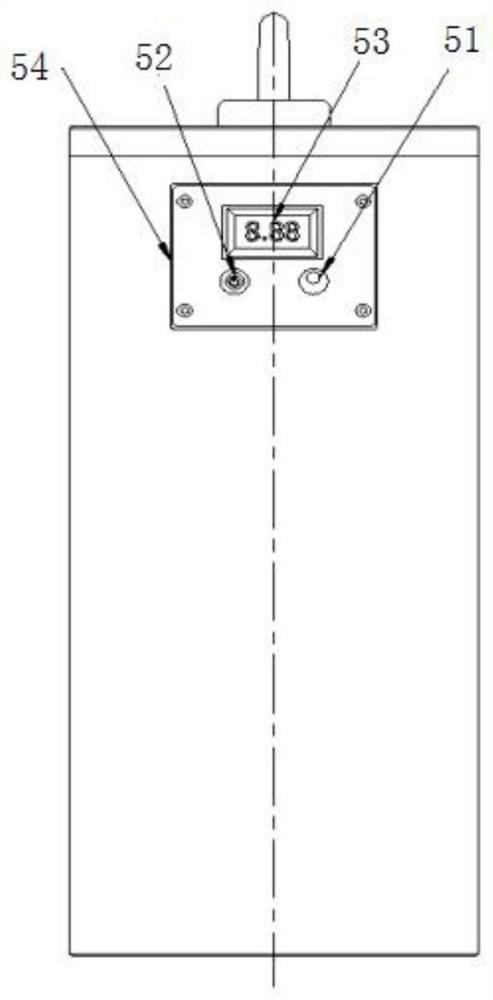
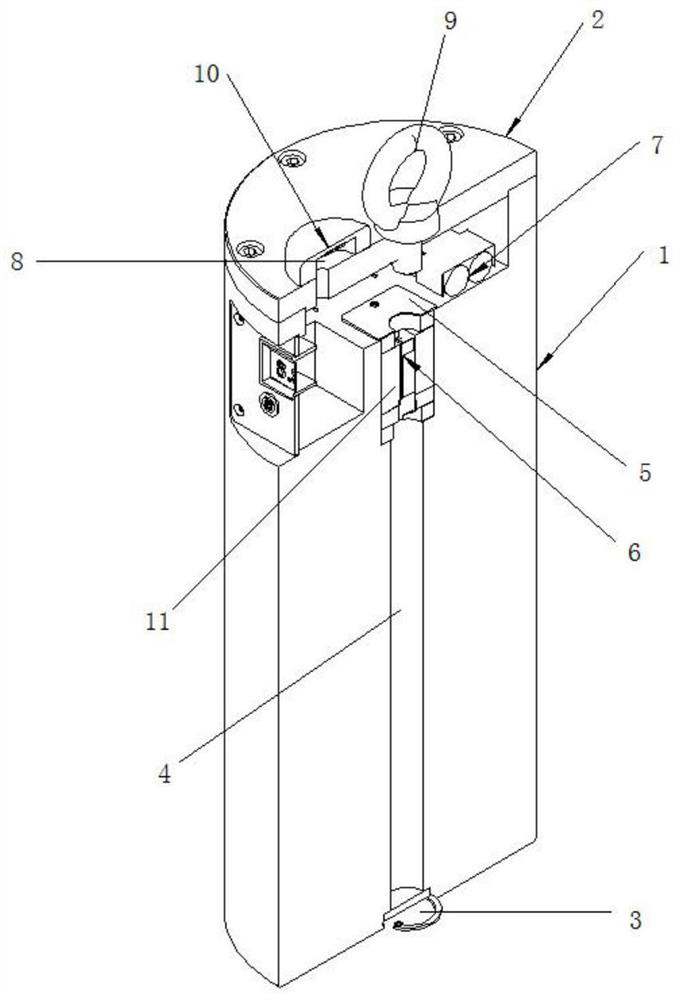
[0031] Open the power switch 52 on the heavy block body 1, the remote control module 5 starts, the antenna receives the signal, the laser distance measuring module 6 starts to work, and the heavy block body 1 is lifted by the lifting ring bolt 9 equipment at the top of the heavy block. The laser ranging module 6 of the block body 1 measures the distance between the weight body 1 and the ground in real time through the laser window 3, and then displays the data through the signal receiving device 8 to obtain accurate measurement values.


PUM


Abstract

The invention discloses a laser ranging weight. The laser ranging weight includes: the weight body, the upper cover of the weight, the laser window, the laser window channel, the remote control module, the laser ranging module, the charging module, the signal receiving device and the eyebolt, the weight body and the weight on the The cover fits and is fixedly connected, the eyebolt is located in the middle of the surface of the upper cover of the weight, the signal receiving device is located on the surface of the upper cover of the weight, the remote control module and the laser ranging module are arranged on the body of the weight and the upper cover of the weight On the central axis, the laser ranging module is located in the upper half of the central axis of the weight body, the charging module is set inside the weight body, and the remote control module controls the laser ranging module to measure the distance between the weight body and the ground through the signal receiving device. The window is set in the middle of the bottom surface of the weight body, and the laser window channel is between the laser window and the laser ranging module. The invention can solve the problems of small ranging range and low safety of the existing laser ranging weight.

Description

technical field [0001] The invention relates to the field of laser ranging, in particular to a laser ranging weight. Background technique [0002] In the existing intelligent laser weight, a laser range finder is provided at the bottom of the weight body, a protective device is provided between the laser range finder and the bottom surface of the weight body, a buffer pad is provided outside the laser range finder, and the weight body A control device for controlling the operation of the laser range finder is also fixed on the side wall of the middle part. Open the control device set on the weight body, and lift the weight body through the lifting equipment. When lifting, the laser rangefinder set in the weight body measures the distance between the weight body and the ground, and passes signal receiving device for display. [0003] The laser distance measuring module is set at the bottom of the weight body, which cannot be measured at close range, which makes short-distan...

Claims


Application Information

Patent Timeline
Patent Type & Authority Patents(China)
IPC IPC(8): B66C13/46
CPCB66C13/46
Inventor 路利军周玉静刘颖华袁丽霞郝捷
Owner 保定市汇邦电气有限公司
Learn More