Fully automatic wire winding machine
A fully automatic winding machine and wire-drawing machine technology, which is applied in the direction of conveying filamentous materials, thin material processing, transportation and packaging, etc. It can solve the problems of occupying a lot of space, low winding quality, and wire quality that cannot meet the requirements, etc. question
- Summary
- Abstract
- Description
- Claims
- Application Information
AI Technical Summary
Problems solved by technology
Method used
Image
Examples
Embodiment 1
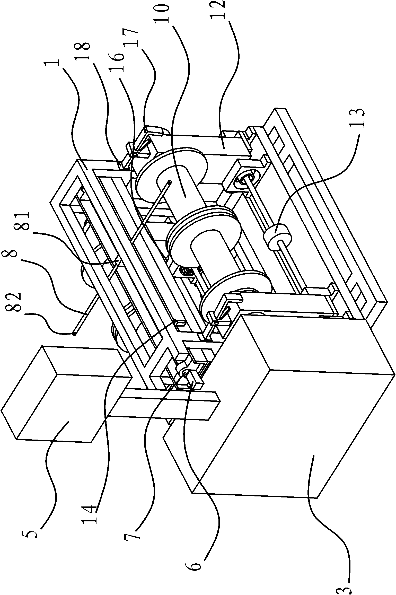
[0043] Such as figure 1 and 5 As shown, the automatic winding machine is connected with the traction machine, and the traction machine is connected with the outlet machine. The automatic winding machine includes a base 1, a detection device, a control cabinet 3 based on PLC4 control, and a The man-machine interface 5, the detection device and the man-machine interface 5 are all connected to the control cabinet 3, and the machine base 1 is provided with a wire feeding and arranging mechanism, a wire winding mechanism and a wire taking mechanism. The detection device in this embodiment is Hall sensor-2.
[0044] The wire feeding and arranging mechanism includes a servo motor 6, a screw mandrel 7, a guide rod 8 and a guide rod support 81 arranged on the machine base 1, one end of the screw mandrel 7 is connected with the motor shaft of the servo motor 6, and the outer peripheral wall of the screw mandrel 7 There is an external thread, the guide rod support 81 has an internal th...
Embodiment 2
[0053] The differences between this embodiment and Embodiment 1 are:
[0054] Such as Figure 6 and 7As shown, the wire feeding and arranging mechanism of the present embodiment includes a sliding bottom plate 22 that is arranged on the machine base 1 and can slide back and forth on the machine base 1, fixing seats 23 fixed on both ends of the sliding bottom plate 22, and an inverted wire. Rod 24, guide rod 8, guide rod support 81, guide shaft 25, motor 28, cylinder 26 and air pump 27, all pass through screw mandrel 24 and guide shaft 25 on two fixed seats 23, and guide shaft 25 is positioned at Between the reversing screw mandrel 24 and the sliding base plate 22, one end of the reversing screw mandrel 24 extends out of the fixed seat 23 and is connected to the motor 28 through a gear, and the guide rod support 81 is provided with a screw guide hole 29 and a shaft guide hole 30 and passes through The screw guide hole 29 and the shaft guide hole 30 are respectively sleeved on...
PUM
 Abstract
Description
Claims
Application Information
 - Generate Ideas
- Intellectual Property
- Life Sciences
- Materials
- Tech Scout
- Unparalleled Data Quality
- Higher Quality Content
- 60% Fewer Hallucinations
Browse by: Latest US Patents, China's latest patents, Technical Efficacy Thesaurus, Application Domain, Technology Topic, Popular Technical Reports.
© 2025 PatSnap. All rights reserved.Legal|Privacy policy|Modern Slavery Act Transparency Statement|Sitemap|About US| Contact US: help@patsnap.com


