
Transformer type sensor circuit system

A sensor circuit and transformer-type technology, applied in the field of sensors, can solve problems such as difficult implementation, poor sensitivity, and increased sensor volume, and achieve the effects of reducing the number of coil turns, excellent performance, and convenient manufacturing

Inactive Publication Date: 2012-10-31
蒋勤舟
View PDF0 Cites 0 Cited by
  • Summary
  • Abstract
  • Description
  • Claims
  • Application Information

AI Technical Summary

Problems solved by technology

[0003] However, these circuits still have several significant disadvantages: First, the sensitivity is poor, and a coil with sufficient turns, such as 2000 turns, is required for better processing
The number of turns of the coil is too many, so the size of the sensor cannot be reduced
[0004] Second, the temperature drift is large
The differential structure requires a symmetrical coil structure, which increases the complexity and process difficulty of the sensor, further increases the volume of the sensor, and increases the manufacturing and installation costs of the sensor
[0005] Third, the output curve is single
For other types of output curves, such as exponential and broken lines, it is difficult to achieve

Method used


Image

  • Transformer type sensor circuit system
  • Transformer type sensor circuit system
  • Transformer type sensor circuit system

Examples


Embodiment Construction

[0048] The present invention will be described in further detail below in conjunction with the accompanying drawings and specific embodiments.

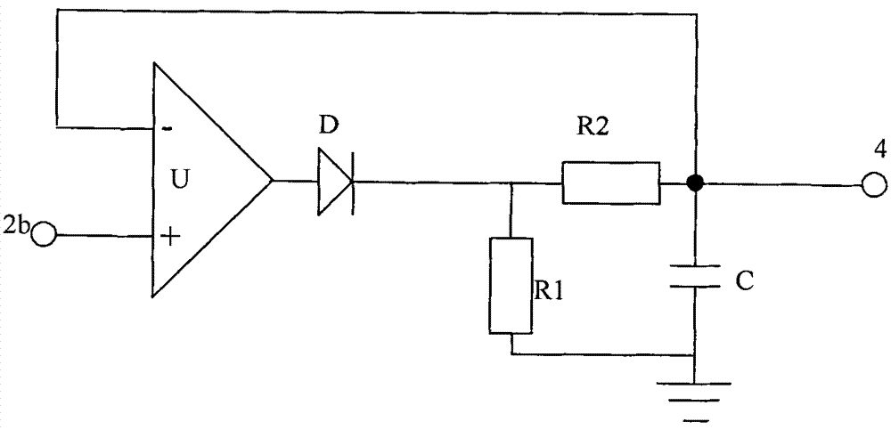
[0049] Such as figure 1 Shown: a transformer-type sensor circuit system, provided with an oscillating drive circuit 1, the output end of the oscillating drive circuit 1 is connected to the primary coil 2a of the transformer sensor, and the secondary coil 2b of the transformer sensor is connected to the processing circuit Above, the output end of the processing circuit is connected with the first output circuit 4 , and the processing circuit is a peak detection circuit 3 .

[0050] The oscillating drive circuit 1 is a pulse switch circuit, and the pulse switch circuit is a rectangular pulse drive circuit sent by a single-chip microcomputer, or an RC oscillating pulse drive circuit, or an LC oscillating pulse drive circuit, or is output after an alternating current coupling capacitor Peak pulse drive circuit.

[0051] In the known tec...


PUM


Abstract

The invention discloses a transformer type sensor circuit system which is provided with an oscillation driving circuit. The output end of the oscillation driving circuit is connected with a primary coil of a variable pressure transformer, a secondary coil of the variable pressure transformer is connected with a processing circuit, and the output end of the processing circuit is connected with a first output circuit. The transformer type sensor circuit system is characterized in that the processing circuit is a peak value detection circuit. The invention has the advantages of reducing the number of turns of the coils of the transformer, and realizing miniaturization, low power consumption and low temperature drift of the sensor. The invention has excellent performance, can more conveniently manufacture the transformer type sensor and can be applied to more conditions.

Description

technical field [0001] The invention belongs to the technical field of sensors, in particular to a transformer-type sensor special circuit. Background technique [0002] Differential transformer sensor is a device that converts the measured non-electrical quantity change into the change of coil mutual inductance. This kind of sensor is mainly made according to the principle of transformer. Because this type of sensor has the advantages of simple structure and high sensitivity, it is widely used For displacement measurement. The coil output of the transformer sensor is an AC signal, which needs to be converted and processed by a circuit to be effectively used. The traditional solution is to use a phase-sensitive detection circuit composed of diodes, or a frequency modulation, phase modulation circuit, etc. [0003] However, these circuits still have several significant disadvantages: first, the sensitivity is poor, and a coil with a sufficient number of turns, such as 2000 ...

Claims


Application Information

Patent Timeline
Patent Type & Authority Patents(China)
IPC IPC(8): G01B7/02
Inventor 蒋勤舟
Owner 蒋勤舟
Learn More