Magnetic suspension train
A magnetic levitation and levitation device technology, which is applied to electric vehicles, vehicle components, electric traction, etc., can solve the problems of complex structure and high cost of magnetic levitation trains, and achieve the effect of simple structure, low cost and strong magnetic force
- Summary
- Abstract
- Description
- Claims
- Application Information
AI Technical Summary
Problems solved by technology
Method used
Image

Examples
Embodiment 1
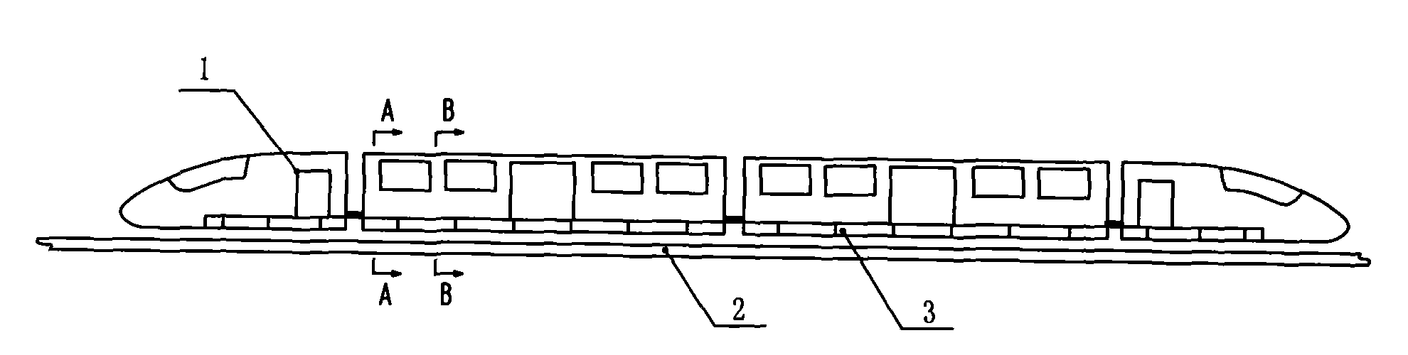
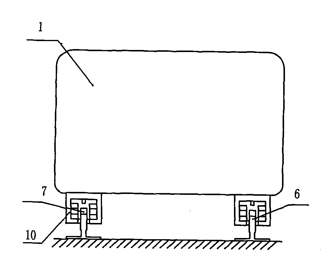
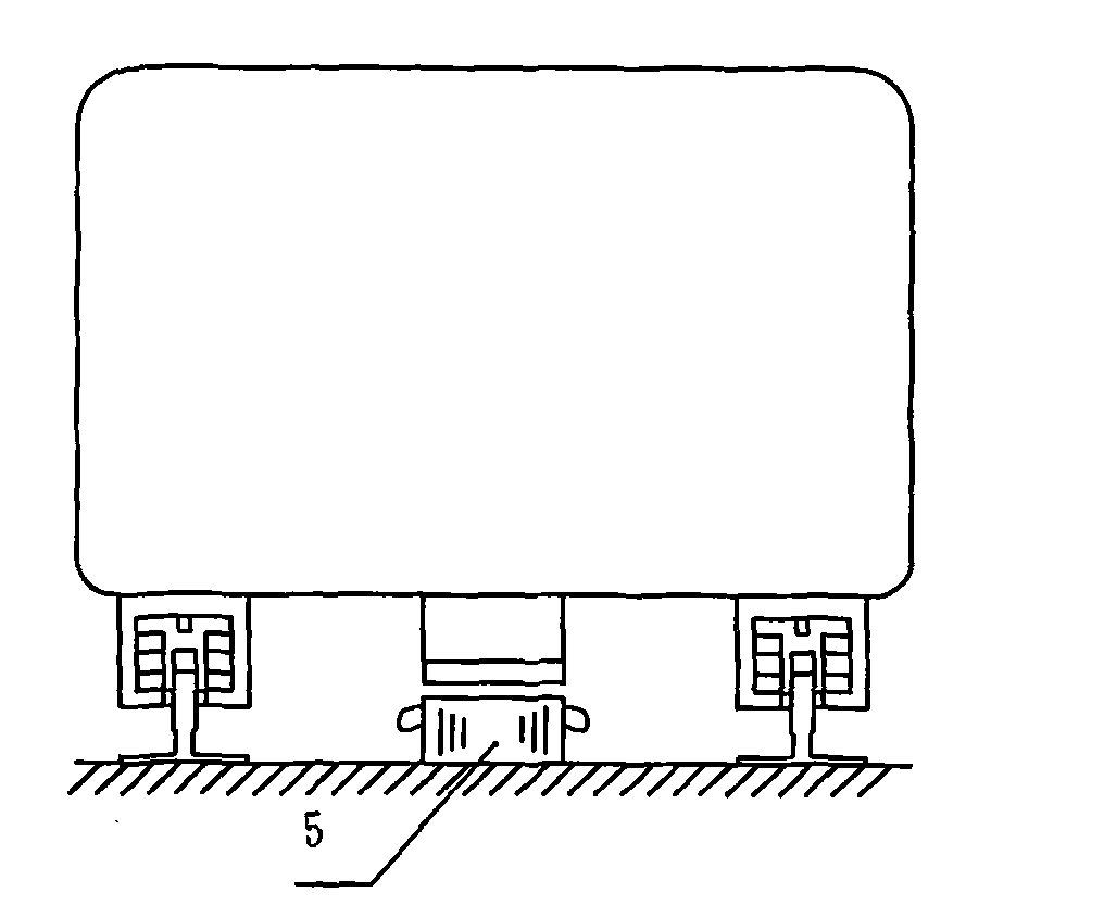
[0042] Such as figure 1 , figure 2 and image 3 As shown, a magnetic levitation vehicle includes a vehicle body 1 and a track. A linear motor power source and two magnetic levitation devices are arranged between the vehicle body and the roadbed. The magnetic levitation device is a reluctance magnetic force levitation device 3 . The yoke I7 and the yoke frame 6 of the reluctance type magnetic levitation device form a track, and the magnet and the magnet frame 10 are fixed on the bottom of the car body. The linear motor is a linear induction motor 5, and the linear induction motor 5 is arranged between the vehicle body and the roadbed. The primary of the linear induction motor 5 is fixed on the bottom of the car body, and the secondary is fixed on the roadbed. The positions of the primary and secondary can be reversed. The magnetic levitation device can be a column, such as Figure 24 shown.
Embodiment 2
[0044] Such as Figure 23 As shown, the linear motor is a linear induction motor 5, and the two primary stages of the linear induction motor 5 are fixed on the inside of the motor frame 14 in parallel, and a track is arranged between the two primary stages. The track is the secondary of the linear induction motor 5, along the In the track direction, the motor frame 14 and the magnet frame 10 are arranged at intervals and fixed on the bottom surface of the car body.
Embodiment 3
[0046] Such as Figure 4 As shown, the linear motor is a permanent magnet linear motor 12, the permanent magnet linear motor 12 is set upside down, the bottom of the car body is fixed with an L-shaped bracket 8, and the roadbed is fixed with an inverted L-shaped bracket 9 corresponding to the L-shaped bracket. A permanent magnet linear motor 12 is arranged between 8 and the inverted L-shaped support 9. The secondary of the permanent magnet synchronous linear motor 12 is fixed on the upper end of the L-shaped support, and the primary is fixed on the lower end of the inverted L-shaped support. The permanent magnet linear motor arranged upside down is fixed at the middle part of the vehicle bottom. or as Figure 5 As shown, the permanent magnet linear motor arranged upside down is fixed on both sides of the vehicle body. Other structures are with embodiment 1.
[0047] Figure 1~5 and Figure 23 , 24 The magnetic levitation device described in is like the bar-shaped reluct...
PUM
 Abstract
Description
Claims
Application Information
 - Generate Ideas
- Intellectual Property
- Life Sciences
- Materials
- Tech Scout
- Unparalleled Data Quality
- Higher Quality Content
- 60% Fewer Hallucinations
Browse by: Latest US Patents, China's latest patents, Technical Efficacy Thesaurus, Application Domain, Technology Topic, Popular Technical Reports.
© 2025 PatSnap. All rights reserved.Legal|Privacy policy|Modern Slavery Act Transparency Statement|Sitemap|About US| Contact US: help@patsnap.com