
Method and system for switching link between evolved node Bs and evolved node Bs

A technology for evolving base stations and link switching, which is applied in the field of communication and can solve problems such as excessive load and overload

Active Publication Date: 2010-10-27
CHINA MOBILE COMM GRP CO LTD
View PDF0 Cites 24 Cited by
  • Summary
  • Abstract
  • Description
  • Claims
  • Application Information

AI Technical Summary

Problems solved by technology

[0005] Embodiments of the present invention provide a method, system and evolved base station for link switching between evolved base stations, so as to solve the overload problem caused by the excessive load of eNB

Method used


Image

  • Method and system for switching link between evolved node Bs and evolved node Bs
  • Method and system for switching link between evolved node Bs and evolved node Bs
  • Method and system for switching link between evolved node Bs and evolved node Bs

Examples


Embodiment 1

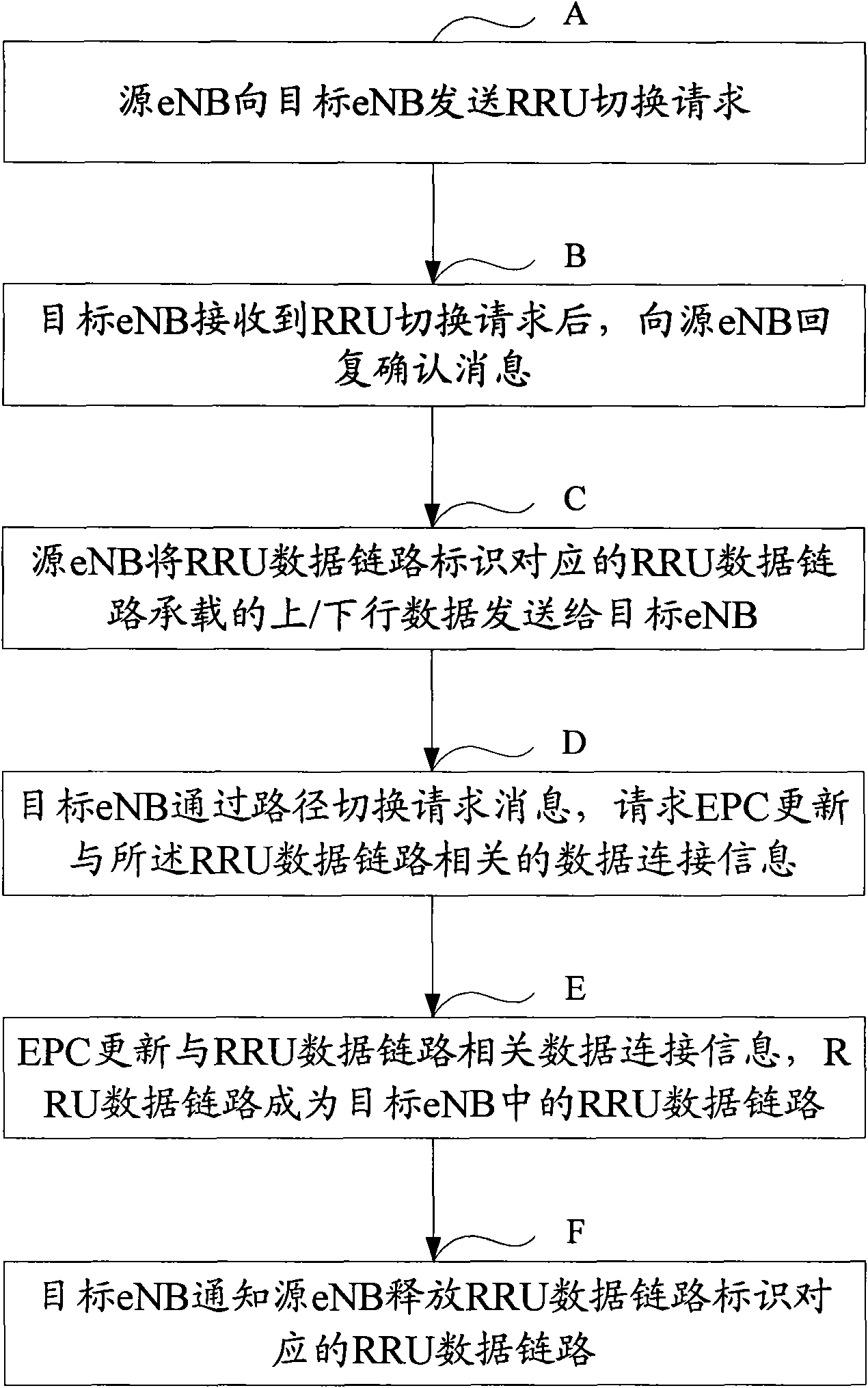
[0064] In step 106 of the first embodiment, the source eNB switches the RRU data link corresponding to the RRU data link identifier to the target eNB. image 3 shown, including the following steps:

[0065] Step A: The source eNB sends an RRU handover request to the target eNB, and the RRU handover request includes: source eNB identifier, RRU data link identifier and data connection context information related to UE.

[0066] The source eNB identifier is used to inform the target eNB that the source eNB is the source of the handover, the RRU data link to be handed over is the RRU of the source eNB, and the data connection context information related to the UE includes SAE Bearer and QoS, etc. are used to indicate the target eNB Information about the UE served by the RRU to be handed over, so that the service of the UE will not be interrupted after the handover.

[0067] The RRU handover request may further include data connection information related to the core network (EPC),...


PUM


Abstract

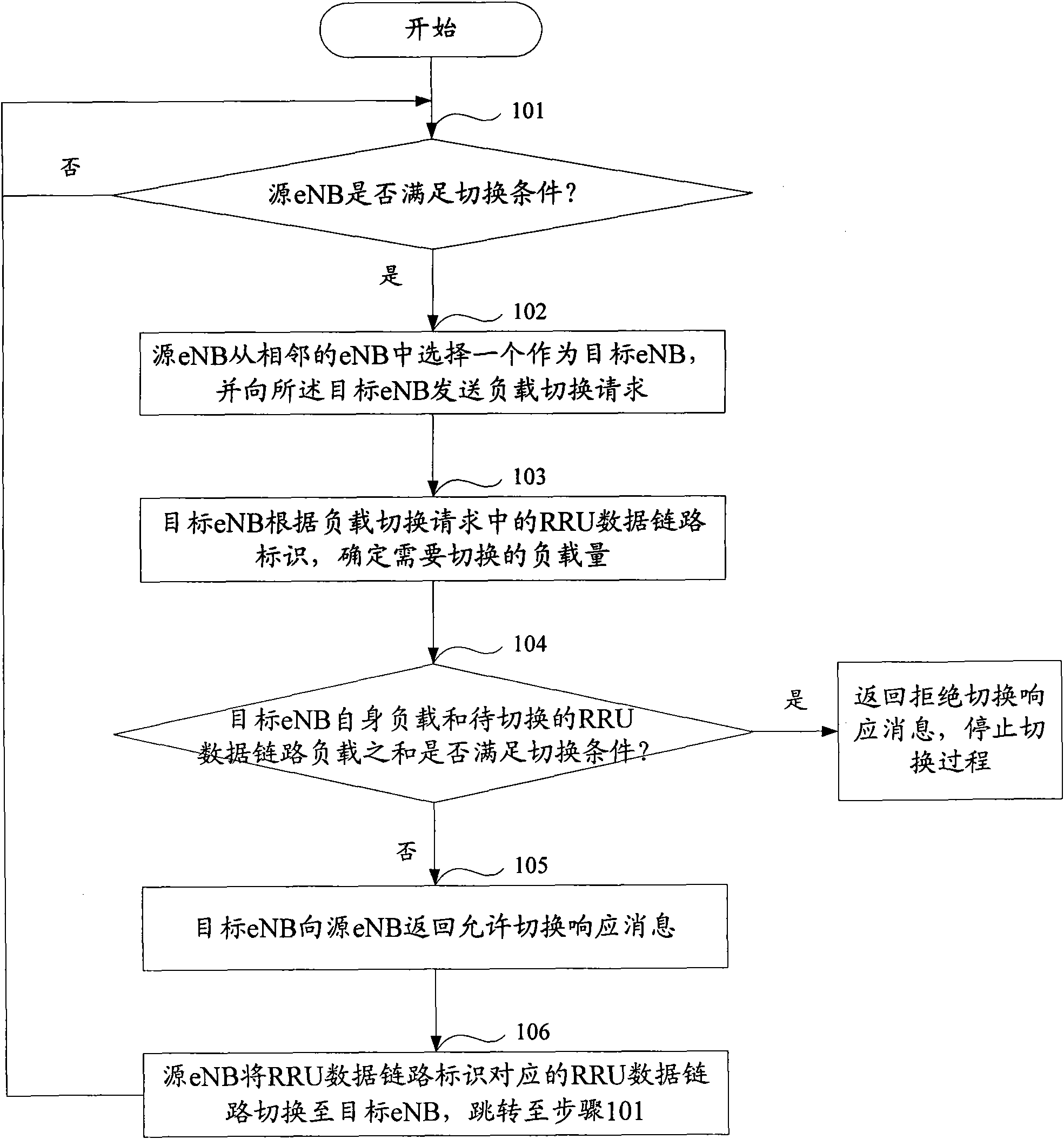
The invention discloses a method for switching a link between evolved node Bs (eNBs), which comprises the following steps that: a source eNB sends a first load switching request to an adjacent eNB when the load state of the source eNB per se meets the switching condition, wherein the first load switching request contains a data link identifier of at least one RRU in the source eNB; and the source eNB switches an RRU data link corresponding to the RRU data link identifier to a target eNB when receiving a switching allowance response message returned by the target eNB. Through the method, the load needing to be processed is transferred to the adjacent eNB when the eNB is overloaded, so that resource sharing between the eNBs which are adjacent to each other is realized, and the problem that one eNB is overloaded due to burst telephone traffic is effectively solved. The invention also discloses a system for switching the link between the eNBs and the eNBs.

Description

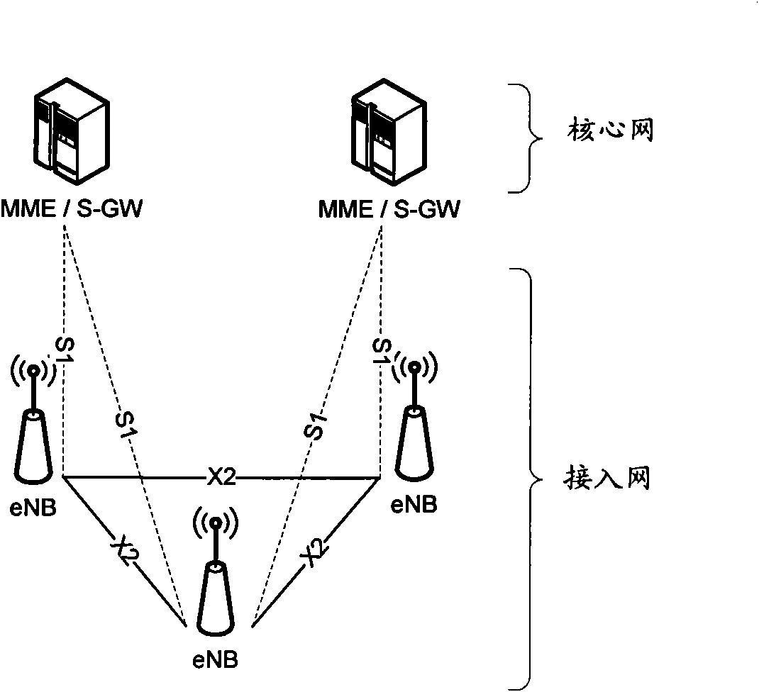
technical field [0001] The present invention relates to the communication field, and in particular to a method, a system and an evolved base station for link switching between evolved base stations. Background technique [0002] Continuing the characteristics of the existing 3GPP mobile communication system, the LTE system architecture includes two parts, one part is the evolved core network (Evolved Packet Core, EPC), including mobile management entity gateway (MME / S-GW) and other equipment, and the other part is It is an evolved access network (Evolved Universal Terrestrial Radio Access Network, E-UTRAN), including devices such as an evolved base station (Evolved Node B, eNB), and its structure is as follows figure 1 shown. The MME / S-GW communicates with the eNB through the S1 interface. In the access network, in order to reduce the user's transmission delay, the architecture design tends to be flatter than that of the 3G system, and only includes multiple eNBs. [0003]...

Claims


Application Information

Patent Timeline
Patent Type & Authority Applications(China)
IPC IPC(8): H04W36/08H04W48/20
Inventor 陈沫闫志刚
Owner CHINA MOBILE COMM GRP CO LTD
Learn More