Constant temperature electronic oscillation equipment

An electronic oscillation and constant temperature technology, applied in the direction of electrical components, temperature control without auxiliary power supply, impedance network, etc., can solve the problems of inconvenient disassembly, easy deviation from the heating area, and difficulty in adjusting the working temperature of the resonant crystal, so as to improve heat insulation performance effect

Inactive Publication Date: 2010-10-27
上海鸿晔电子科技股份有限公司
View PDF0 Cites 0 Cited by
  • Summary
  • Abstract
  • Description
  • Claims
  • Application Information

AI Technical Summary

Problems solved by technology

However, the adhesive has the problem that it is easy to age and fall off, which leads to the unstable position of the resonant crystal, and it is easy to shift out of the heating area, and then it is difficult to adjust the working temperature of the resonant crystal.
Another disadvantage of using adhesive is that it is inconvenient to disassemble and the resonant crystal cannot be replaced at will

Method used


Image

  • Constant temperature electronic oscillation equipment
  • Constant temperature electronic oscillation equipment
  • Constant temperature electronic oscillation equipment

Examples


Embodiment Construction

[0017] Embodiments of the present invention are described in detail below, and examples of the embodiments are shown in the drawings, wherein the same or similar reference numerals denote the same or similar elements. The embodiments described below with reference to the figures are exemplary and are intended to explain the present invention, and should not be construed as limiting the present invention.

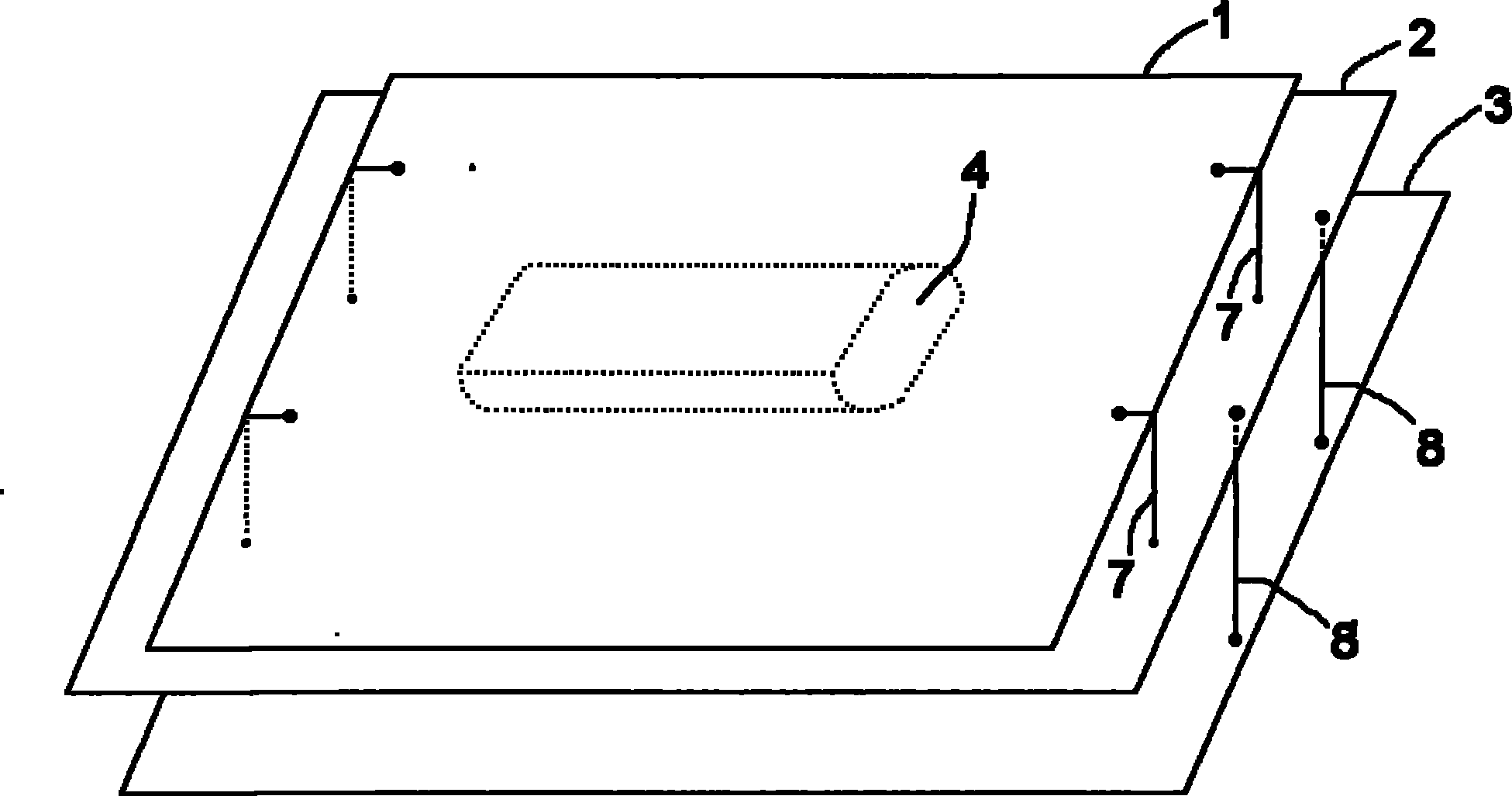
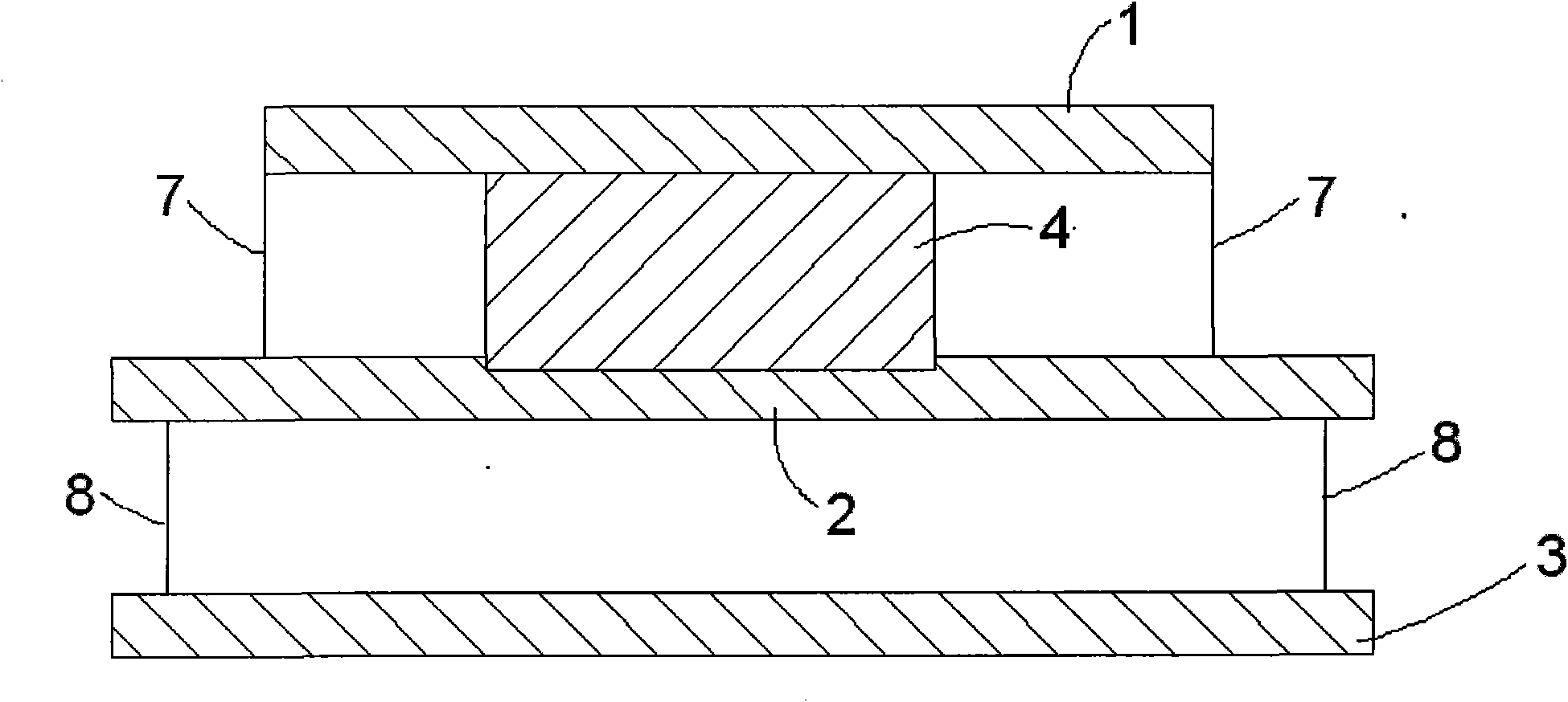
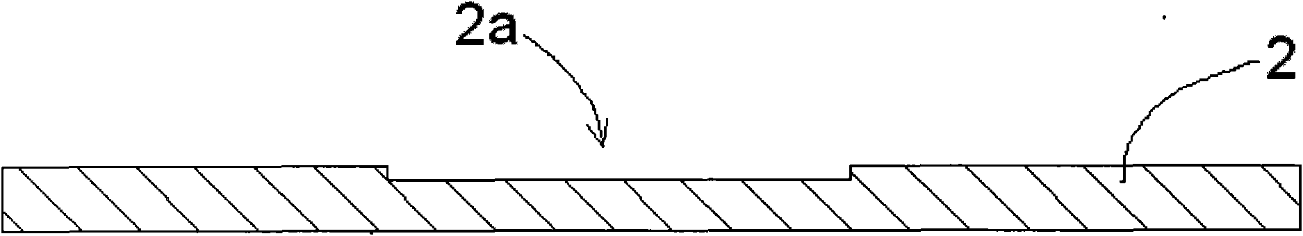
[0018] figure 1 A schematic diagram showing the three-dimensional structure of the constant temperature electronic oscillation device of the present invention; figure 2 A longitudinal sectional view showing the constant temperature electronic oscillation device of the present invention; image 3 A longitudinal sectional view showing the lower printed circuit board of the constant temperature electronic oscillation device of the present invention; and Figure 4 A longitudinal sectional view showing the constant temperature electronic oscillating device of the present inven...


PUM


Abstract

The invention discloses constant temperature electronic oscillation equipment which comprises an upper layer printed circuit board, a lower layer printed circuit board, a bottom plate, a resonance crystal and a shell. The lower layer printed circuit board is electrically and supported with the upper layer printed circuit board through a lead, the bottom plate is electrically and supported with the lower layer printed circuit board through a lead, the resonance crystal is clamped between the upper layer printed circuit board and the lower layer printed circuit board, the shell is used for containing the upper layer printed circuit board, the lower layer printed circuit board and the resonance crystal in a sealing way, and a locating groove used for containing and locating the resonance crystal is arranged in at least one of the upper layer printed circuit board and the lower layer printed circuit board. Compared with the prior art, the invention has the advantages of reliable location and easy change of the resonance crystal because the locating groove used for containing and locating the resonance crystal is arranged in at least one of the upper layer printed circuit board and the lower layer printed circuit board.

Description

technical field [0001] The invention relates to a constant temperature electronic oscillation device. Background technique [0002] Oven Controlled Crystal Oscillator includes a printed circuit board and a resonant crystal. Because the resonant crystal must work at a constant temperature. Therefore, a heating device must be provided on the printed circuit board to adjust the temperature of the resonant crystal so that it can work at a constant temperature. In the prior art, the resonant crystal is generally pasted on the heating device by an adhesive. However, the adhesive has the problem that it is easy to age and fall off, which leads to the unstable position of the resonant crystal, and it is easy to shift out of the heating area, and then it is difficult to adjust the working temperature of the resonant crystal. Another disadvantage of using adhesive is that it is inconvenient to disassemble and the resonant crystal cannot be replaced at will. Contents of the invent...

Claims


Application Information

Patent Timeline
Patent Type & Authority Applications(China)
IPC IPC(8): H03H9/13G05D23/01
Inventor 杨勇姜伟伟李昕黄然
Owner 上海鸿晔电子科技股份有限公司
Why Eureka
Try Eureka