Driving apparatus, optical apparatus, and driving signal control circuit
A technology for driving signals and driving devices, applied in optics, optical components, installation, etc., can solve problems such as complex action sound control
- Summary
- Abstract
- Description
- Claims
- Application Information
AI Technical Summary
Problems solved by technology
Method used
Image

Examples
no. 1 Embodiment approach
[0046] As the imaging device (optical device) having the driving device in the first embodiment, for example, the imaging optical system and the imaging element are relatively moved in a direction perpendicular to the optical axis direction to perform hand-shake correction (vibration prevention). That is, the camera shake is corrected by moving the imaging optical system according to hand shake, and changing the relative position to the imaging element. This imaging device is applied to a camera that captures a still image, a video camera that captures a moving image, an imaging unit mounted in a mobile phone, and the like.
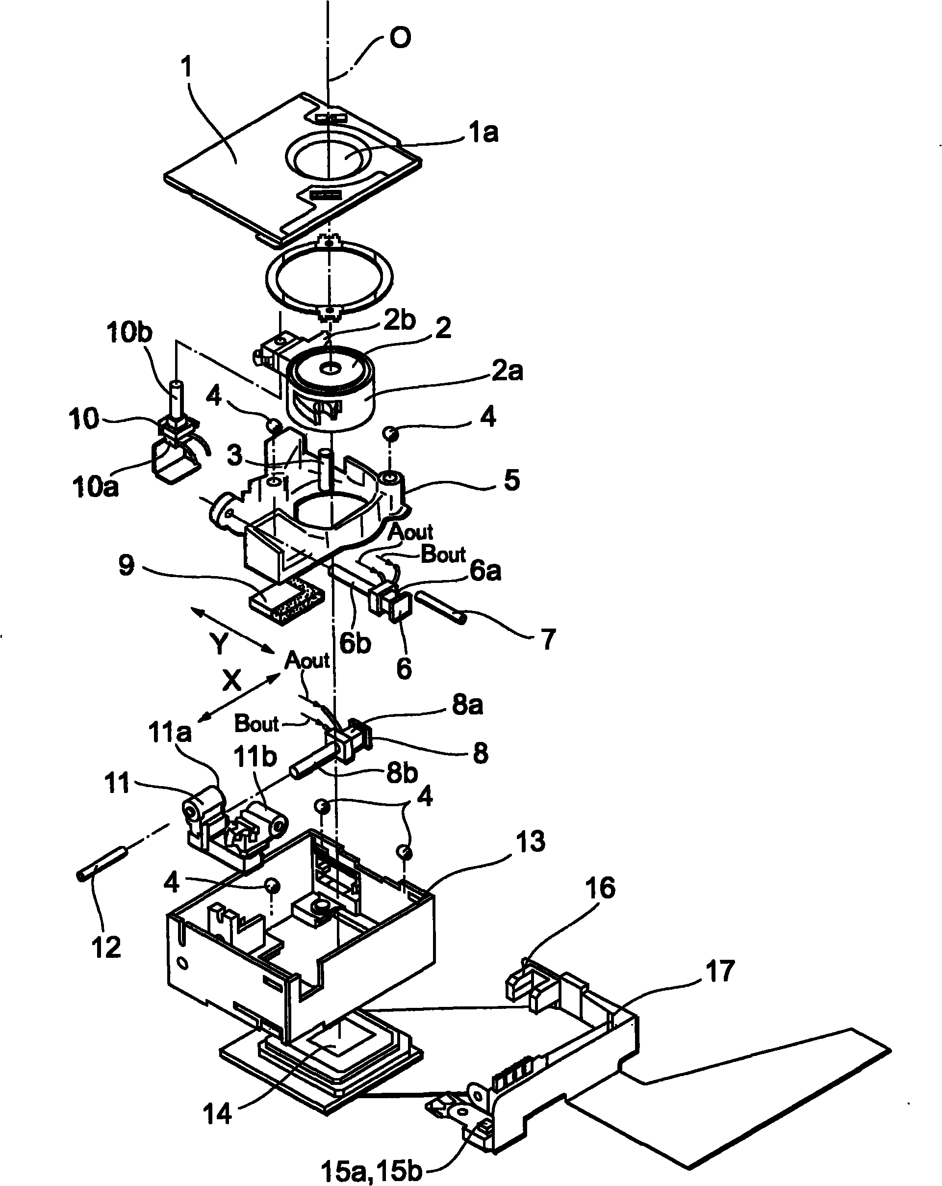
[0047] First, the mechanical structure of an imaging device having a driving device in this embodiment will be described. figure 1 It is an exploded perspective view of an imaging unit and a hand-shake correction mechanism in the imaging device having the driving device according to the first embodiment. Such as figure 1As shown, the imaging device incl...
no. 2 Embodiment approach
[0108] The imaging device having the driving device in the second embodiment has substantially the same configuration as the imaging device in the first embodiment, and only the operation of the first control unit 30 is different from the imaging device in the first embodiment. In addition, in the second embodiment, descriptions of parts that overlap with those of the first embodiment will be omitted, and differences will be mainly described.
[0109] First, the configuration of an imaging device including the driving device in the second embodiment will be described. The first control unit 30 of the drive device in the second embodiment has a function of controlling the application time of the stop control pulse signal. Other functions are the same as those of the first control unit 30 of the first embodiment.
[0110] Next, the anti-vibration operation of the imaging device having the driving device in the second embodiment will be described. Figure 12 It is a flowchart sho...
no. 3 Embodiment approach
[0123] The imaging device having the driving device in the third embodiment has substantially the same configuration as the imaging device having the driving device in the first embodiment, and only the first control unit is compared with the imaging device having the driving device in the first embodiment. 30 moves differently. In addition, in the third embodiment, overlapping parts with the first embodiment or the second embodiment will be omitted, and differences will be mainly described.
[0124] First, the configuration of an imaging device including the driving device in the third embodiment will be described. The first control unit 30 of the drive device in the third embodiment has the function of controlling the application time of the stop control pulse signal, as in the second embodiment. Other functions are the same as those of the first control unit 30 of the first embodiment.
[0125] Next, the anti-vibration operation of the imaging device having the driving de...
PUM
 Abstract
Description
Claims
Application Information
 - R&D
- Intellectual Property
- Life Sciences
- Materials
- Tech Scout
- Unparalleled Data Quality
- Higher Quality Content
- 60% Fewer Hallucinations
Browse by: Latest US Patents, China's latest patents, Technical Efficacy Thesaurus, Application Domain, Technology Topic, Popular Technical Reports.
© 2025 PatSnap. All rights reserved.Legal|Privacy policy|Modern Slavery Act Transparency Statement|Sitemap|About US| Contact US: help@patsnap.com