Production method of metal framework composite hose

A composite hose and metal skeleton technology, applied in the direction of hoses, pipes, pipes/pipe joints/pipe fittings, etc., can solve problems such as damage, elongated pipe body, difficult to pull out, etc., and achieve the effect of convenient use and improved quality

Inactive Publication Date: 2012-08-08
沈阳海洋轻型软管有限公司
View PDF0 Cites 0 Cited by
  • Summary
  • Abstract
  • Description
  • Claims
  • Application Information

AI Technical Summary

Problems solved by technology

[0002] Previously, the method of domestic production of this kind of metal skeleton composite hose was roughly the same; all kinds of materials were wound and wrapped on a metal core, and one end of the metal core was fixed after the metal skeleton composite hose was formed. The metal skeleton composite hose is pulled down from the other end of the metal core; the pipe body is stretched a lot, and the metal skeleton composite hose is bound to be more or less affected or even damaged
The longer the metal skeleton composite hose is produced by this method, the harder it is to pull it out. If the method is not mastered properly, the metal skeleton composite hose will be seriously deformed when the pipe is pulled out for a length of more than 12 meters, and it is prone to damage and fracture.
The metal skeleton composite hose produced by this method may not be able to stop the pressure even if it is pulled out, and it is difficult to guarantee the service life even if the pressure is temporarily stopped, so the length of this metal skeleton composite hose is basically limited to 16 meters within
In addition, multiple metal-skeleton composite hoses must be connected during long-distance transportation. Each joint includes flanges, etc., ranging from a few kilograms to tens of kilograms, which is inconvenient and poses a safety hazard.

Method used


Image

  • Production method of metal framework composite hose
  • Production method of metal framework composite hose
  • Production method of metal framework composite hose

Examples


Embodiment 1

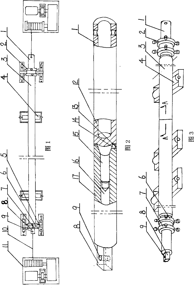
[0020] Embodiment 1: process the 15-meter-long metal skeleton composite flexible pipe 3, adopt a pipe core 1, and its steps are as follows:

[0021] The first step is to arrange the double chain rings 2 on both sides of the die 1 respectively;

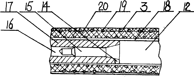
[0022] In the second step, lubricating oil is applied outside the tube core 1, and then the padding 18 is wound outside the lubricating oil (the padding 18 can be plastic);

[0023] The 3rd step, wrap steel wire 19, plastic cloth 20, steel wire 19 to form metal frame composite flexible pipe 3 (this is conventional technology, can adopt different steel wire 19, plastic cloth 20 according to user's needs) successively outside pad cloth 18;

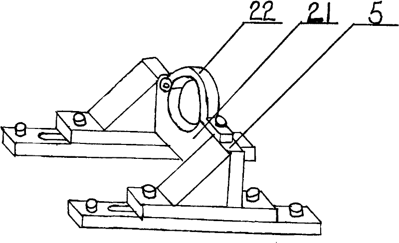
[0024] The fourth step is to place the metal skeleton composite hose 3 on the support roller 4 between the winches 11, loosen the tube core positioning ring 7 of the double chain 2 respectively, and move the metal through the fixed ring 21 and the movable ring 22 of the positioning frame 5. The fram...

Embodiment 2

[0025] Embodiment 2: process the 30-meter-long metal skeleton composite hose 3, adopt two tube cores 1, i.e. the left tube core 17, the right tube core 12, and its steps are as follows:

[0026] The first step, first, combine the inner hole 16 of the left die 17 with the positioning rod 15 of the right die 12, and combine the shifting block 14 of the right die 12 with the groove 13 of the left die 17, that is, the left die 17 1. The right tube core 12 is combined to form a tube core 1; the double chain rings 2 are respectively arranged on both sides of the tube core 1;

[0027] In the second step, lubricating oil is applied outside the tube core 1, and then the padding 18 is wound outside the lubricating oil (the padding 18 can be plastic);

[0028] The third step, fix the positioning block 8 on the end of the left tube core 17 on the center hole of the machine tool head, fix the end of the right tube core 12 on the top of the machine tool; 1. Wrap steel wire 19, plastic clot...


PUM


Abstract

The invention relates to a production method of a metal framework composite hose, which is widely applied in the fields of oil ports and wharfs, ships in river and sea, oil refining, pharmaceutical chemicals, metallurgical coking, storage and transportation and the like and meets the requirements of conveying various liquid and gases. The invention provides a production method capable of improving production quality and also producing a long metal framework composite hose. The invention adopts the following production steps: step 1, coating lubricating oil at the outside of a tube core, and then winding cloth liner at the outside of the lubricating oil; step 2, winding and wrapping steel wires, plastic cloths and steel wires in sequence at the outside of the cloth liner to form the metal framework composite hose; and step 3, fixing the metal framework composite hose, then drawing the tube core, leading the tube core to be out of the cloth liner and then taking out the cloth liner.

Description

Technical field: [0001] The invention relates to a production method of a metal skeleton composite hose. The metal skeleton composite hose is widely used in the fields of oil port terminals, river and sea ships, petroleum refining, pharmaceutical chemical industry, metallurgical coking, storage and transportation, etc., and can meet the needs of transporting various liquids. and gas needs. Background technique: [0002] Previously, the method of domestic production of this kind of metal skeleton composite hose was roughly the same; all kinds of materials were wound and wrapped on a metal core, and one end of the metal core was fixed after the metal skeleton composite hose was formed. The metal skeleton composite hose is pulled down from the other end of the metal core; the pipe body is elongated a lot, and the metal skeleton composite hose is bound to be more or less affected or even damaged. The longer the metal skeleton composite hose is produced by this method, the harde...

Claims


Application Information

Patent Timeline
Patent Type & Authority Patents(China)
IPC IPC(8): F16L11/10F16L11/24
Inventor 孟凡涛
Owner 沈阳海洋轻型软管有限公司
Why Eureka
Try Eureka