
Modularized roll surface for moving article

A modular, flat technology, applied in the direction of rollers, rollers, conveyor objects, etc., which can solve problems such as surface damage, low total resistance, and object advancement.

Active Publication Date: 2010-10-27
FM LTD
View PDF4 Cites 9 Cited by
  • Summary
  • Abstract
  • Description
  • Claims
  • Application Information

AI Technical Summary

Problems solved by technology

Thus for each lateral thrust applied to and transmitted from the roller to the frame, only one of the two sides resists the thrust; therefore, not only is the overall resistance of the roller plane to lateral stress lower, but the deformation of the stressed side will be actually present, this is enough to cause the pivot to leave the base associated to the other side, and therefore the rollers at the base of the frame will fall
[0006] Another limitation of prior art solutions manifests itself in permissible low load values ​​and excessive loads (even for short periods) that cannot be supported above low load values; under these conditions the pivot or roller-bracket breaks because the pivot Shafts and brackets are the main parts that will be stressed in the entire structure protruding between the sides of the frame
[0007] Finally, in known construction solutions, the various modules that make up the roller planes of the conveyor line consist of ends that lack mutual hooking
Thus if the connection between the two modules is carried out with the roller plane in the protruding area, additional specific means of rigid connection of the frames of the two modules must be provided which, among other things, must be able to ensure During this passage through the plane of the rollers, no step between the two modules occurs after deflection due to the weight of the item itself; this step could cause problems with the advancement of the item or could even cause surface damage to the item itself

Method used


Image

  • Modularized roll surface for moving article
  • Modularized roll surface for moving article
  • Modularized roll surface for moving article

Examples


Embodiment Construction

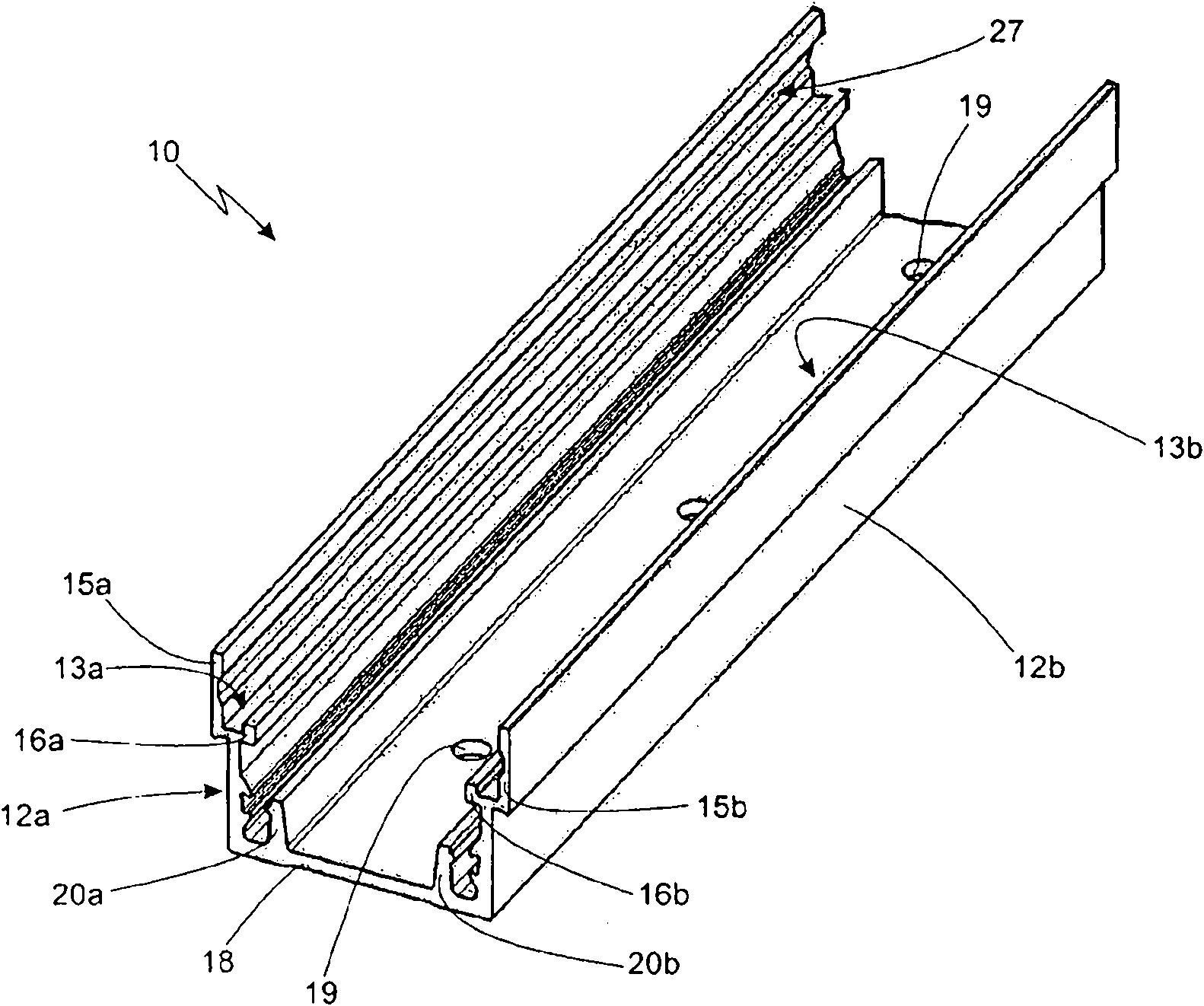
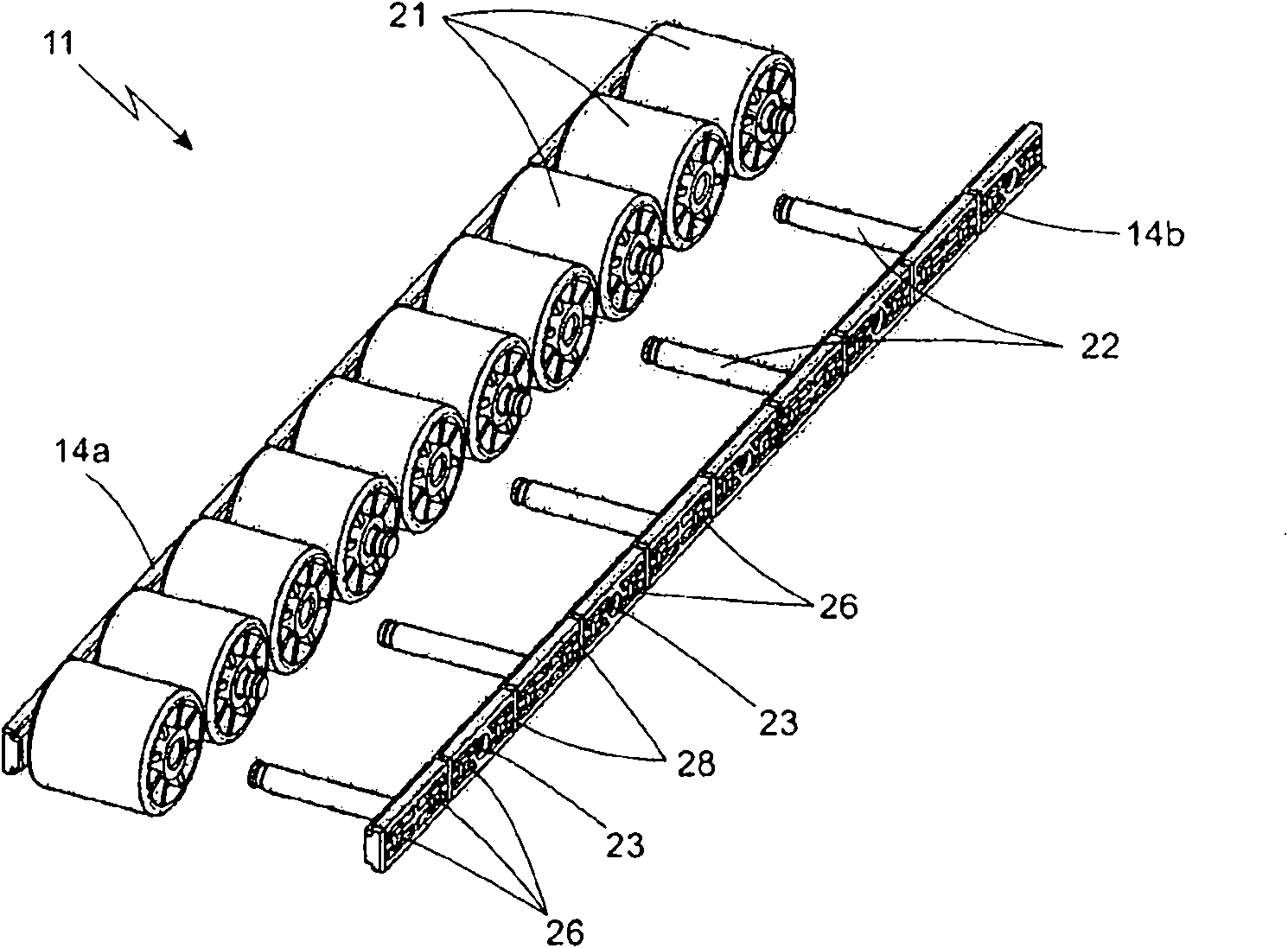
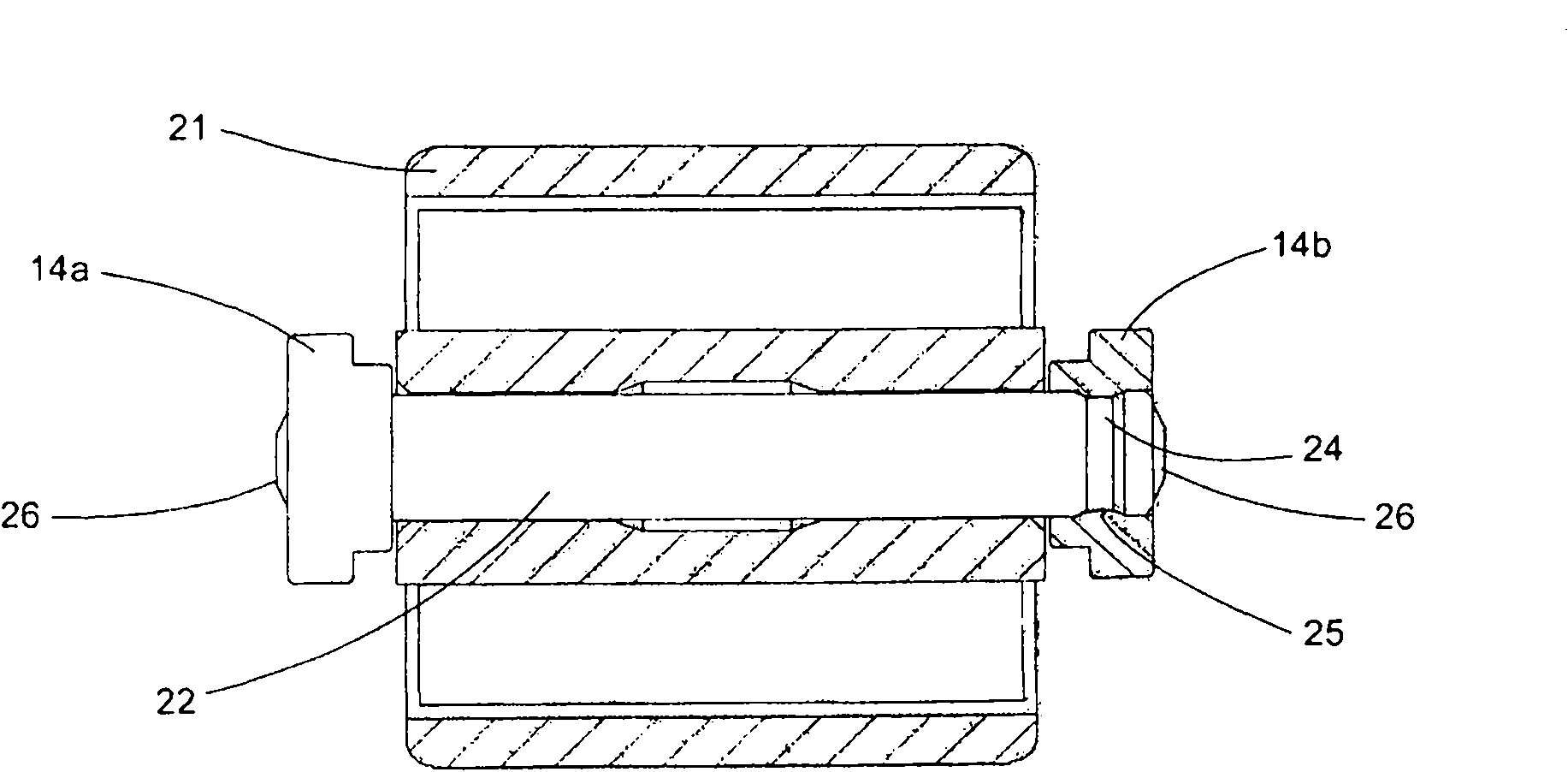
[0026] refer to figure 1 , 10 denotes a support frame for a roller plane for moving light items along a conveyor line, the base of a processing machine, a gravity-operated warehouse, or other similar applications, where, in particular, the conveyed items have features that require protection from scratches or Dented exterior surface. The frame, preferably manufactured from extruded aluminum profiles, is substantially U-shaped and is intended to receive e.g. Figure 5 At least one roller bracket 11 is shown in. To this end, the frame 10 comprises two sides 12a, 12b in which longitudinal seats 13a, 13b for receiving the outer longitudinal bars 14a, 14b of the support 11 are formed. The longitudinal base 13a, 13b comprises an outer wall 15a, 15b and an inner protrusion 16a, 16b parallel to the outer wall and at a distance therefrom equal to Figure 4 The width of the longitudinal bars 14a, 14b of the bracket 11 can be seen in . The inner protrusions 16a, 16b allow the bracket...


PUM


Abstract

The invention discloses a modularized roll surface for moving an article on a conveying line or a base of a processor or for other application. The modularized roll surface comprises a support framework (10) preferably made of metal elements, and a roll bracket (11) with rolls (21) is buckled and inserted into the support framework. The grouped rolls of the bracket are arranged in the support framework, the disassembly operation of the rolls can be easily and elastically executed by using the structure of the framework, and the maintenance of the roll surface and the structural operation of anchoring the framework to the conveying line are convenient. Assembly of the grouped rolls of the bracket actually is easily realized through the specific configuration of the bracket and materials for manufacturing the rolls. Modularity of the roll surface is obtained by using specific connecting elements of the framework with the bracket; and the bracket with any proper length can be obtained.

Description

technical field [0001] The present invention relates to a roller plane for moving articles along conveyor lines, bases of processing machines, machines operated by gravity or other similar applications. Background technique [0002] The roller plane consists of rollers rotating according to a rotation axis perpendicular to the advancing direction of the article, wherein rollers having a diameter of about several centimeters and a substantially considerable length are gathered in a support frame containing a predetermined number of rollers. These can be mounted individually and directly on the frame or can be pre-collected in roller bearing brackets which are then inserted longitudinally into the supporting frame. [0003] In both solutions involving the mounting of the rollers individually in the frame and of the frame-roller group formation, there are operational difficulties when installing the rollers and when they are being maintained. [0004] An important consideratio...

Claims


Application Information

Patent Timeline
IPC IPC(8): B65G13/00B65G13/11B65G13/12
CPCB65G39/12B65G13/11
Inventor G·弗朗奇尼
Owner FM LTD
Learn More