
Device and method for transmitting camera signals

A signal transmission and camera technology, applied in the field of data transmission, can solve the problems of asynchronous output line synchronization signal of the camera, weak anti-interference ability, complex circuit design, etc., achieve simple circuit design, save the number of transmission ports, and reduce signal attenuation Effect

Inactive Publication Date: 2012-02-08
GUANGDONG VTRON TECH CO LTD
View PDF0 Cites 1 Cited by
  • Summary
  • Abstract
  • Description
  • Claims
  • Application Information

AI Technical Summary

Problems solved by technology

In the existing camera signal transmission methods, although some also adopt the DVI interface to realize the remote control camera module of the camera signal processing module, the signal attenuation is serious, the anti-interference ability is not strong so that the reliability is not high, and the circuit design is complicated , the number of pins such as 18+1 or 24+1 of the DVI interface is required, and each camera requires a large number of connecting lines for remote control; some use the method of separate transmission of camera data signals and field signals to reduce the occupation of pins The quantity, but it brings problems such as out-of-sync between chips, causing the camera output data to be out of sync with the camera output field sync signal and the camera output line sync signal

Method used


Image

  • Device and method for transmitting camera signals
  • Device and method for transmitting camera signals
  • Device and method for transmitting camera signals

Examples


Embodiment

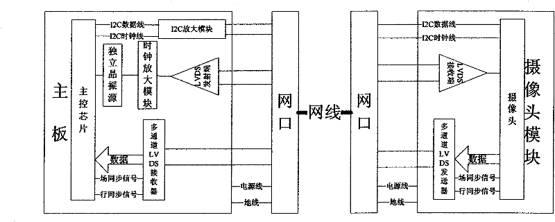
[0026] Such as figure 1 As shown, the camera signal transmission device of the present invention includes a main board and a camera module connected to each other by a network cable, wherein the main board includes a main control chip, a crystal oscillator source connected to the main control chip, and a multi-channel LVDS receiver; the camera module includes a phase connection camera, a multi-channel LVDS transmitter. The main control chip is connected to the camera through an I2C interface and a network cable; the crystal oscillator source is an independent crystal oscillator source, and is connected to the camera through a differential circuit composed of an LVDS transmitter and an LVDS receiver. The camera output data, the camera output field synchronization signal and the camera output line synchronization signal are differentially output through the multi-channel LVDS transmitter, and are input to the main control chip through the multi-channel LVDS receiver at the main ...


PUM


Abstract

The invention provides a device and a method for transmitting camera signals. The device comprises a main board and a camera module and is characterized in that: the main board and the camera module are mutually connected through a network cable; the main board comprises a main control chip, and a crystal oscillation source and a multi-channel LVDS transmitter, which are respectively connected with the main control chip; and the camera module comprises a camera and a multi-channel LVDS receiver, which are connected with each other. The device of the invention has the advantages of guaranteeing that the camera data signals are strictly transmitted under the action of horizontal and vertical synchronous signals, along with low cost, simple circuit design and few long-distance control connecting wires of the camera.

Description

technical field [0001] The invention relates to the technical field of data transmission, in particular to a camera signal transmission device and method. Background technique [0002] In some application fields, the camera module and the camera signal processing module are on the same board, and long-distance transmission is not required; but in some applications, the camera module and the camera signal processing module need to be separated, that is, the camera shooting and the camera signal processing module need to be separated. The camera signal processing is not on the same board. At this time, the camera signal needs to be transmitted over a long distance. In the existing camera signal transmission methods, although some also adopt the DVI interface to realize the remote control camera module of the camera signal processing module, the signal attenuation is serious, the anti-interference ability is not strong so that the reliability is not high, and the circuit design...

Claims


Application Information

Patent Timeline
Patent Type & Authority Patents(China)
IPC IPC(8): H04N7/10
Inventor 陈伟钦钟杰婷
Owner GUANGDONG VTRON TECH CO LTD
Learn More