
Telephone interface circuit of automatic detection alarm tester for communication cable breakpoint

An automatic detection and communication cable technology, applied in the electronic field, can solve the problems of complex network layout, inability to adapt to the development of communication industry, and low efficiency

Inactive Publication Date: 2012-07-25
SHANDONG UNIV OF SCI & TECH
View PDF0 Cites 0 Cited by
  • Summary
  • Abstract
  • Description
  • Claims
  • Application Information

AI Technical Summary

Problems solved by technology

[0002] With the rapid development of modern communication, there are more and more communication lines of various types, and the network layout is complex. With the development of cities, the excavation of urban roads is also increasing, so that communication lines are not only affected by natural forces, but also communication cables appear. The situation of breakpoints is also affected by some human factors, such as road excavation and cable theft, which cause breakpoints in communication cables, which affect the operation of the entire communication network
How to grasp the on-off status of various communication cables in a timely and reliable manner, at present, only when there is a breakpoint fault in the communication cable, only use special tools to detect the on-off of the communication line on site. The efficiency of this detection method is relatively low. A lot of manpower and material resources are wasted, which brings great difficulties to the timely maintenance of communication cables, and cannot adapt to the development of the communication industry, affecting the service quality of the entire communication industry

Method used


Image

  • Telephone interface circuit of automatic detection alarm tester for communication cable breakpoint
  • Telephone interface circuit of automatic detection alarm tester for communication cable breakpoint
  • Telephone interface circuit of automatic detection alarm tester for communication cable breakpoint

Examples


Embodiment Construction

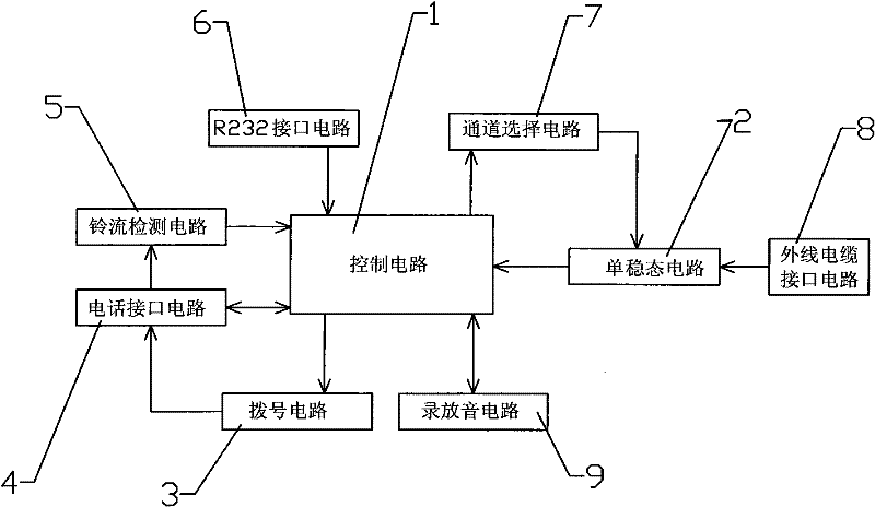
[0017] Examples such as figure 1 As shown, the telephone interface circuit of the communication cable breakpoint automatic detection alarm device includes an electrically connected control circuit 1, a monostable circuit 2, a dialing circuit 3, a telephone interface circuit 4, a ring current detection circuit 5, an R232 interface circuit 6, and a channel Selection circuit 7, external cable interface circuit 8 and recording and playback circuit 9.

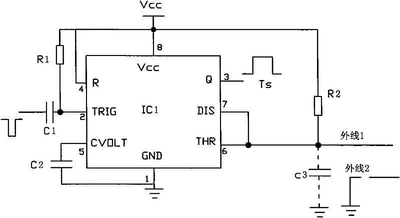
[0018] Such as figure 2 As shown, only a pair of cables are drawn in the figure. The monostable circuit 2 includes an integrated circuit IC1, a capacitor C1, a capacitor C2, a resistor R1 and a resistor R2. The integrated circuit IC1 is a 555 integrated circuit, and the ground terminal of the integrated circuit IC1 is The capacitor C2 is connected to the control voltage terminal CVOLT of the integrated circuit IC1, the trigger terminal TRIG of the integrated circuit IC1 is connected to one end of the capacitor C1 and one end of th...


PUM


Abstract

The invention relates to a telephone interface circuit of an automatic detection alarm tester for a communication cable breakpoint. The alarm comprises a control circuit, a dial circuit and a telephone interface circuit, wherein the telephone interface circuit comprises an amplifying circuit and a trigger circuit; the amplifying circuit comprises an operational amplifier IC2, an operational amplifier IC3, a resistor R3, a resistor, R4, a resistor R5, a resistor R6, a resistor R7, a capacitor C4, a capacitor C5, a capacitor C6 and a capacitor C7; the inverse input end of the operational amplifier IC2 is connected with one end of the resistor R3; one end of the resistor R4 is connected with one end of the resistor R5; the other end of the resistor R3 is connected with an AUD aural signal via the capacitor C4; and the other end of the resistor R4 is connected with the dial circuit via the capacitor C5. The monostable circuit and the control circuit cooperate to detect the breakpoint of the cable in real time and judge the distance to the breakpoint. When the cable is stolen or breaks down, the telephone interface circuit can quickly measure the distance to the cable breakpoint and dial the prestored telephone number to give an alarm by speech.

Description

technical field [0001] The invention relates to a detection and alarm device, in particular to a telephone interface circuit of the detection and alarm device capable of automatically detecting the breakpoint of a communication cable, and belongs to the field of electronic technology. Background technique [0002] With the rapid development of modern communication, there are more and more communication lines of various types, and the network layout is complex. With the development of cities, the excavation of urban roads is also increasing, so that communication lines are not only affected by natural forces, but also cause communication cables to appear. Breakpoints are also affected by some human factors, such as road excavation and cable theft, which cause breakpoints in communication cables, which affect the operation of the entire communication network. How to grasp the on-off status of various communication cables in a timely and reliable manner, at present, only when t...

Claims


Application Information

Patent Timeline
Patent Type & Authority Patents(China)
IPC IPC(8): H04M11/04G01R31/08
Inventor 王立华王明合
Owner SHANDONG UNIV OF SCI & TECH
Learn More