
Capacitive touch pad with comb-shaped electrode

A capacitive touch and electrode technology, applied in the direction of electrical digital data processing, input/output process of data processing, instruments, etc., can solve the problem of affecting the linear stability of the electric field, failing to meet the use requirements, and water droplets on the touch panel and other problems, to achieve the linear stability of the electric field, maintain a uniform distribution, and improve the effect of accuracy and sensitivity

Inactive Publication Date: 2010-10-06
SHANTOU GOWORLD DISPLAY (PLANT II) CO LTD
View PDF5 Cites 12 Cited by
  • Summary
  • Abstract
  • Description
  • Claims
  • Application Information

AI Technical Summary

Problems solved by technology

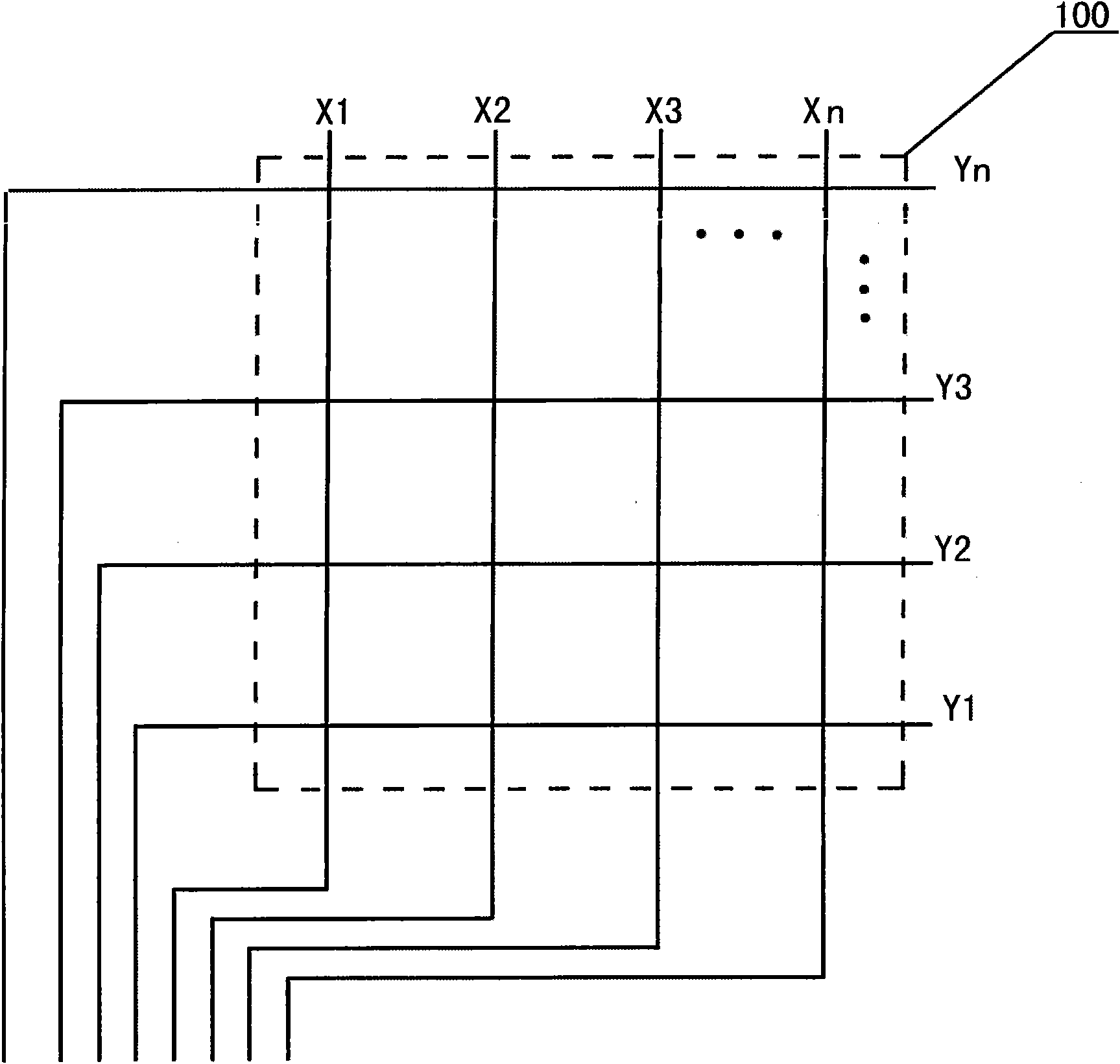
This traditional design method of sensing electrode traces depends on the number of IO ports of the touch chip and the area of ​​the touch panel to determine the density of the electrode traces, resulting in coupling capacitance between the sensing electrodes, or between the sensing electrodes and the human body or the ground. The coupling capacitance is limited, that is, the existing electric field and the electric field generated by touch are limited, which affects the linear stability of the electric field. As a result, the signal sensitivity of the capacitive touch panel on the hardware can only reach a certain level. However, in a special environment, it may not be able to meet the use requirements, such as the touchpad is suspended in the air, or the touchpad is stained with water droplets, etc., and the touch will fail.

Method used


Image

  • Capacitive touch pad with comb-shaped electrode
  • Capacitive touch pad with comb-shaped electrode
  • Capacitive touch pad with comb-shaped electrode

Examples


Embodiment Construction

[0026] Further description will be given below in conjunction with the accompanying drawings and preferred embodiments of the present invention.

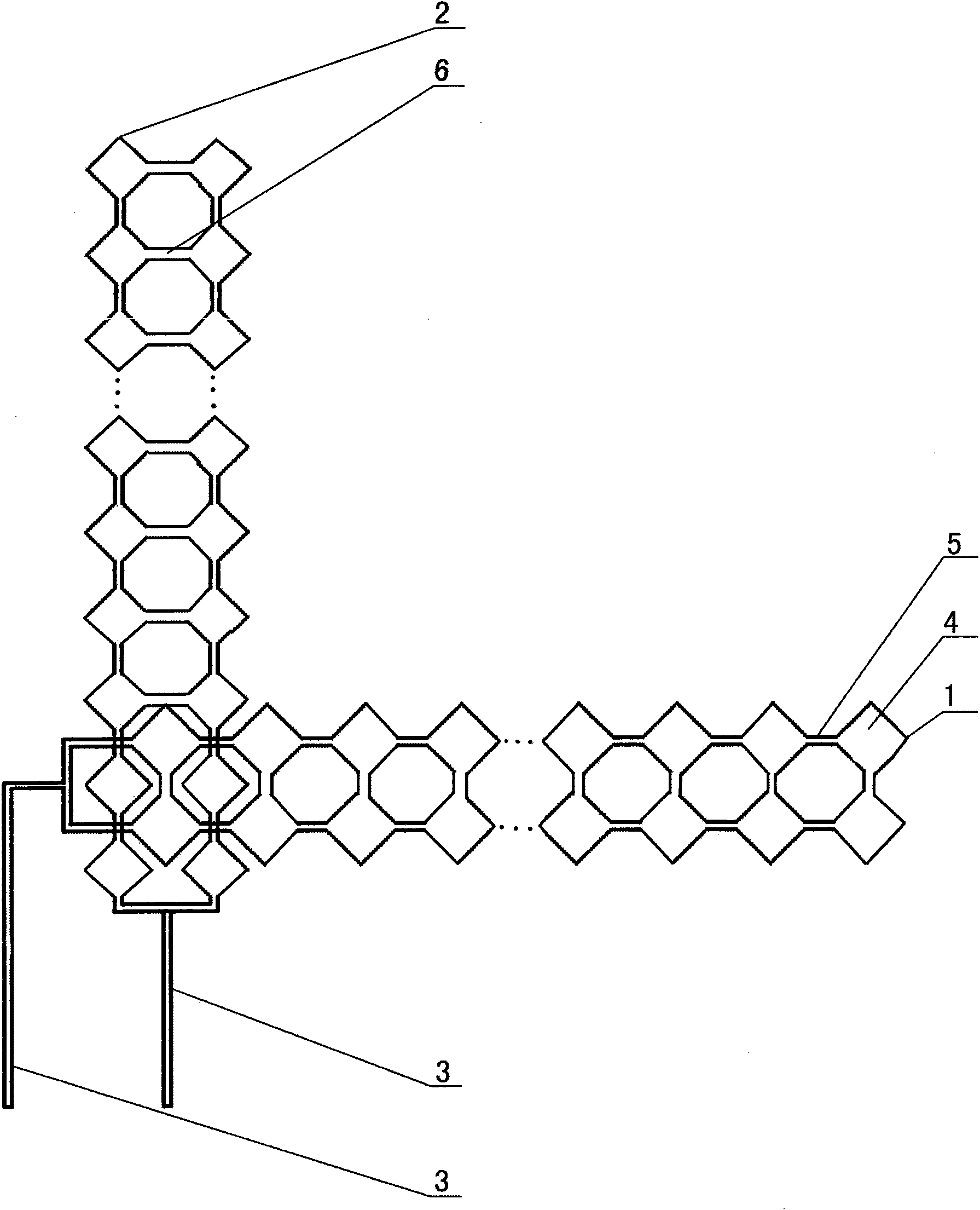
[0027] Such as figure 2 As shown, the capacitive touch panel with comb-shaped electrodes includes a transparent substrate, sensing electrodes and a protective film. The sensing electrodes include a set of horizontal electrode traces 1 and a set of vertical electrode traces 2. The horizontal electrode lines Traces 1 and longitudinal electrode traces 2 are alternately arranged on the transparent substrate, and lead wires 3 that can be connected to the IO ports of the touch chip are also included, and one end of each lead wire 3 is connected to two electrode traces 1 (or 2).

[0028] The horizontal electrode traces 1 and the longitudinal electrode traces 2 both include a plurality of prismatic sensing electrode blocks 4, and the 4 prismatic sensing electrodes are connected by electrode block wiring 5; the electrode traces 1 (or 2) con...


PUM


Abstract

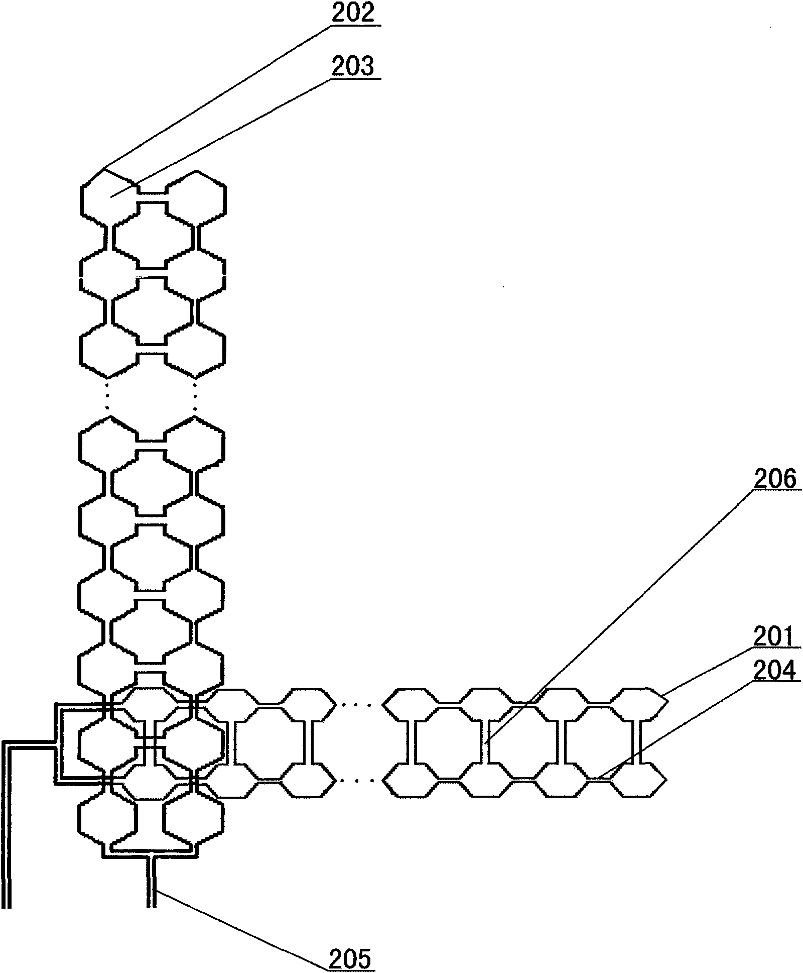
The invention relates to a capacitive touch pad with comb-shaped electrodes, which comprises a transparent substrate and inductive electrodes. The inductive electrodes are arranged on the transparent substrate and comprise a group of transverse electrode wire traces, a group of longitudinal electrode wire traces and leading-out wires connected with the I / O ports of a touch chip, wherein the transverse electrode wire traces intersect with the longitudinal electrode wire traces. The invention is characterized in that at least partial leading-out wires are connected with the electrode wire traces in a way that one leading-out wire corresponds to a plurality of electrode wire traces. By adopting the arrangement, one I / O port of the touch chip corresponds to one leading-out wire and one leading-out wire can correspond to a plurality of electrode wire traces. Thereby, the number of the electrode wire traces in a touch area can be multiplied, the number of the electrodes can be multiplied, the distribution of the electrodes is kept to be even, the density of charges distributed on the capacitive touch pad is enabled to be changed more stably, the linearity of an electric field is enabled to be more stable, the coupling capacitance on the touch area is improved and the accuracy and the sensitivity of the touch pad are improved.

Description

technical field [0001] The invention relates to a touch panel, in particular to a capacitive touch panel with comb electrodes. Background technique [0002] Capacitive touch panels have been widely used in various electronic products, such as mobile phones, mp4, POS terminals and so on. The capacitive touch panel is characterized by high transmittance and no need to apply force when touching, and can resist harsh external environments, such as water, temperature changes, and humidity, so it has a long service life and can realize multiple touch points during work. Simultaneous detection, more user-friendly operation. [0003] The capacitive touch panel generally includes a transparent substrate and sensing electrodes, the sensing electrodes are arranged on the transparent substrate, and the leads of the sensing electrodes are electrically connected to the detection circuit. In the case of setting two transparent substrates, one of the substrates can be used as a dielectric...

Claims


Application Information

Patent Timeline
Patent Type & Authority Applications(China)
IPC IPC(8): G06F3/044
Inventor 林铿郑清交吴锡淳吴永俊沈奕李永忠欧建平游荣鑫杨柳根
Owner SHANTOU GOWORLD DISPLAY (PLANT II) CO LTD
Learn More