Experiment table for testing hydraulic servo system

A technology of hydraulic servo system and test bench, which is applied in the field of test benches, can solve the problems of high cost, high risk, and high risk of experiments, and achieve the effect of reducing experimental risks and costs

Inactive Publication Date: 2012-09-05
TSINGHUA UNIV
View PDF0 Cites 0 Cited by
  • Summary
  • Abstract
  • Description
  • Claims
  • Application Information

AI Technical Summary

Problems solved by technology

In order to further test the influence of the improvement of the control algorithm on the position control performance and force control performance of the servo system, it is necessary to carry out experimental research in the actual mechanical device, but this will cause defects such as high experimental cost, high risk, and high risk.

Method used


Image

  • Experiment table for testing hydraulic servo system
  • Experiment table for testing hydraulic servo system
  • Experiment table for testing hydraulic servo system

Examples


Embodiment 1

[0030] Embodiment 1: Experimental research on force control of a hydraulic cylinder drive unit is carried out.

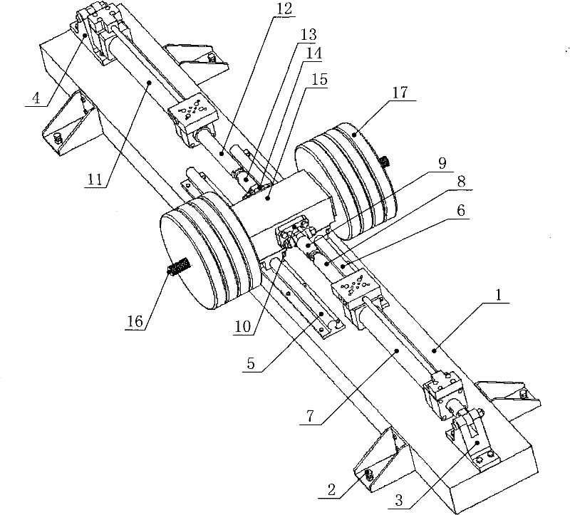
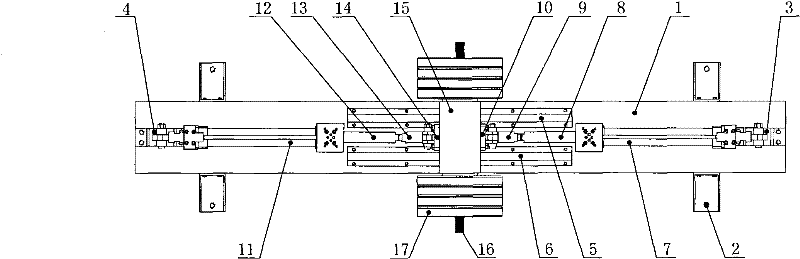
[0031]In this embodiment, the second hydraulic cylinder driving unit can be removed, and the first hydraulic cylinder driving unit drives the slide table 15 to move back and forth along the guide rails 5 and 6, and the control target is the piston rod 8 and the first hydraulic pressure of the first hydraulic cylinder driving unit. The force value of pulling the pressure sensor between the piston rod lugs 9 of the cylinder drive unit. The first hydraulic cylinder drive unit is enabled to generate a desired continuous output force.

Embodiment 2

[0032] Embodiment 2, research on the position servo control of the hydraulic cylinder drive unit under the condition of continuous external load.

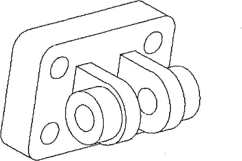
[0033] In this embodiment, the controlled system is a position servo control system composed of the first hydraulic cylinder drive unit, the sliding table 15 and its load 17 . The first hydraulic cylinder driving unit and the second hydraulic cylinder driving unit are installed at the same time, the first hydraulic cylinder driving unit generates continuous external disturbance force, and the first hydraulic cylinder driving unit adopts position control. Under the action of continuous external disturbance force, when different control strategies or algorithms are adopted, the invention can realize the research on the position servo control performance of the controlled system. According to another example of the present invention, the Figure 4 Schematic diagram of the structure of the extended connection block shown. The connect...

Embodiment 3

[0035] Implementation example 3, a position servo control experiment of the hydraulic drive unit is carried out under the condition of discontinuous external force load.

[0036] In this embodiment, the controlled system is a position servo control system composed of the first hydraulic cylinder drive unit, the sliding table 15 and its load 17, etc., and the first hydraulic cylinder drive unit and the second hydraulic cylinder drive unit are installed at the same time. The drive unit of the two hydraulic cylinders adopts force control, and the first lug 13 of the drive unit of the first hydraulic cylinder drives the pin (or bolt) installed on it to slide in the long groove of the extension connecting block 10. The external disturbance force exerted by the position servo control system composed of the drive unit, the slide table 15 and its load 17 is zero. When the pin (bolt) reaches the two ends of the long slot of the extended connection block 10, it starts to exert the desir...


PUM


Abstract

The invention discloses an experiment table for testing a hydraulic servo system. The experiment table comprises a base, a first differential hydraulic cylinder driving unit, a second differential hydraulic cylinder driving unit, a third support lug, a fourth support lug, a sliding table and a supporting rod, wherein the first differential hydraulic cylinder driving unit and the second differential hydraulic cylinder driving unit are symmetrically fixed on the base along the longitudinal direction; the third support lug and the fourth support lug are used for fixing the first differential hydraulic cylinder driving unit and the second differential hydraulic cylinder driving unit on the base respectively; the sliding table is positioned between the first differential hydraulic cylinder driving unit and the second differential hydraulic cylinder driving unit; the sliding table is connected with the first differential hydraulic cylinder driving unit and the second differential hydraulic cylinder driving unit respectively through a first connecting block and a second connecting block; the supporting rod penetrates the side central position of the sliding table along the transverse direction; and loads are arranged on the supporting rod and on the two sides of the sliding table. When the experiment table is used for performing hydraulic pressure servo control experiment research and hydraulic system position servo control research, an experiment on an actual heavy-load big-inertia equipment mechanical system can be moved to a lab, so that the experiment cost and risk can be largely reduced.

Description

technical field [0001] The present invention relates to a test bench, in particular to a test bench for testing a hydraulic servo system, and more particularly to a test bench for testing and improving the performance of a hydraulic servo system under impact conditions. Background technique [0002] At present, in general industrial fields and heavy machinery fields, mechanical systems often work under conditions of external disturbances. In some process links, such as forging process, it is also necessary to control the output force of the mechanical system. In order to ensure that the hydraulic system can have good position servo control performance and output force control stability in the presence of external disturbances, in engineering practice, the flexibility of the hydraulic system or mechanical devices are usually used to solve these two problems. question. With the improvement of product quality and the improvement of mechanical work efficiency, it is of great s...

Claims


Application Information

Patent Timeline
Patent Type & Authority Patents(China)
IPC IPC(8): F15B19/00
Inventor 关立文王立平汪劲松程宁波
Owner TSINGHUA UNIV
Why Eureka
Try Eureka