Anti-flogging device for automobile seat
A car seat, anti-whiplash technology, applied in vehicle seats, special positions of vehicles, vehicle parts and other directions, can solve the problems of high price, general performance, complex structure, etc., achieve low cost, protect occupants, and inhibit upward drift moving effect
- Summary
- Abstract
- Description
- Claims
- Application Information
AI Technical Summary
Problems solved by technology
Method used
Image

Examples
Embodiment 1
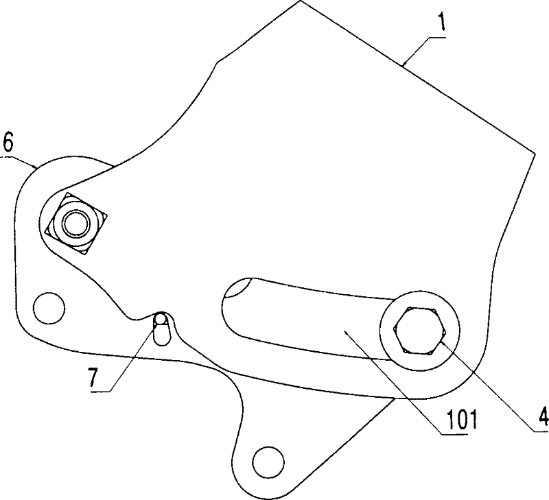
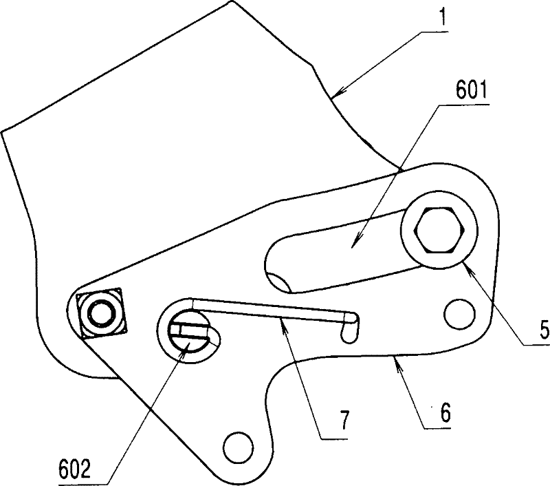
[0024] There is an adjustment groove 101 on the guide plate 1, and a guide groove 601 on the installation plate 6. The adjustment groove roller 2 is socketed with the adjustment groove roller bolt shaft 4, and the adjustment groove roller bolt shaft 4 with rollers is connected to the guide plate 1. The adjustment groove 101 on the top is threaded and connected with the mounting plate 6; the guide groove roller 3 is socketed with the guide groove roller bolt shaft 5, and the guide groove roller bolt shaft 5 with rollers is connected with the mounting plate 6 The guide groove 601 passes through and is threadedly connected with the guide plate 1 ; one end of the control spring 7 is wound around the control spring pin 602 on the mounting plate 6 , and the other end passes through the mounting plate 6 and is engaged with the edge of the guide plate 1 .
Embodiment 2
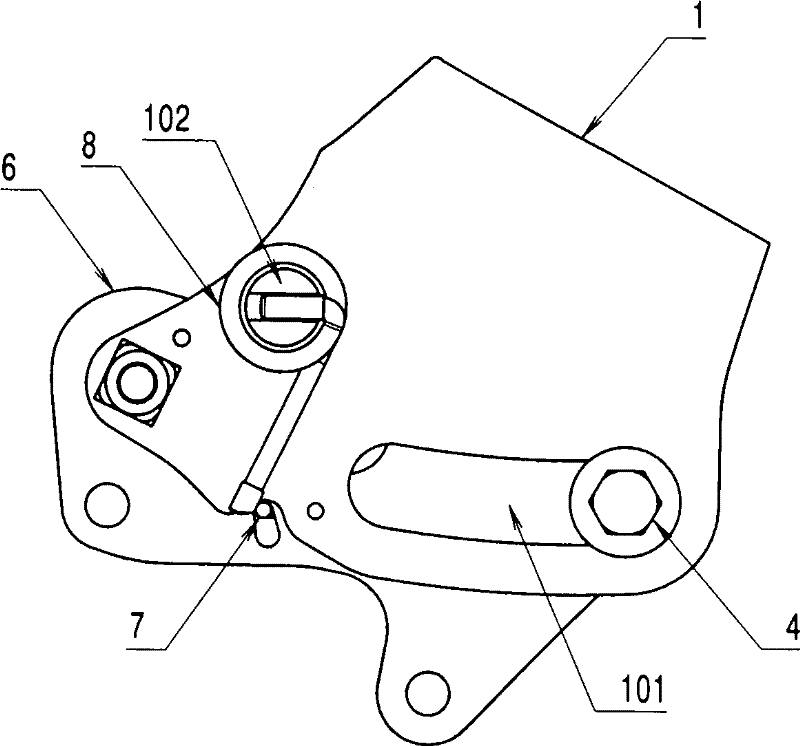
[0026] There is an adjustment groove 101 on the guide plate 1, and a guide groove 601 on the installation plate 6. The adjustment groove roller 2 is socketed with the adjustment groove roller bolt shaft 4, and the adjustment groove roller bolt shaft 4 with rollers is connected to the guide plate 1. The adjustment groove 101 on the top is threaded and connected with the mounting plate 6; the guide groove roller 3 is socketed with the guide groove roller bolt shaft 5, and the guide groove roller bolt shaft 5 with rollers is connected with the mounting plate 6 The guide groove 601 is threaded and connected with the guide plate 1; one end of the locking spring 8 is wound on the locking spring pin 102 on the guide plate 1, and one end of the control spring 7 is wound on the control spring pin on the mounting plate 6 The other end of the shaft 602 passes through the mounting plate 6 and engages with the locking spring 8 .
Embodiment 3
[0028] There is an adjustment groove 101 on the guide plate 1, and a guide groove 601 on the installation plate 6. The adjustment groove roller 2 is socketed with the adjustment groove roller bolt shaft 4, and the adjustment groove roller bolt shaft 4 with rollers is connected to the guide plate 1. The adjustment groove 101 on the top is threaded and connected with the mounting plate 6; the guide groove roller 3 is socketed with the guide groove roller bolt shaft 5, and the guide groove roller bolt shaft 5 with rollers is connected with the mounting plate 6 The guide groove 601 passes through and is threadedly connected with the guide plate 1; the middle part of the lock spring 8 is wound on the lock spring pin 102 on the guide plate 1, one end is hooked with the edge of the guide plate 1, and one end of the control spring 7 is wound around Connected to the control spring pin shaft 602 on the mounting plate 6 , the other end passes through the mounting plate 6 and is engaged wi...
PUM
 Abstract
Description
Claims
Application Information
 - R&D
- Intellectual Property
- Life Sciences
- Materials
- Tech Scout
- Unparalleled Data Quality
- Higher Quality Content
- 60% Fewer Hallucinations
Browse by: Latest US Patents, China's latest patents, Technical Efficacy Thesaurus, Application Domain, Technology Topic, Popular Technical Reports.
© 2025 PatSnap. All rights reserved.Legal|Privacy policy|Modern Slavery Act Transparency Statement|Sitemap|About US| Contact US: help@patsnap.com