Permanent-magnet operating mechanism for circuit breaker

A technology of permanent magnet operating mechanism and circuit breaker, applied in high-voltage air circuit breakers, circuits, power devices inside switches, etc., can solve the problems of poor controllability, high cost, poor reliability, etc. Production cost, effect of good opening and closing characteristics

Inactive Publication Date: 2010-09-29
UNIV OF SCI & TECH OF CHINA
View PDF0 Cites 7 Cited by
  • Summary
  • Abstract
  • Description
  • Claims
  • Application Information

AI Technical Summary

Problems solved by technology

This improved circuit breaker operating mechanism solves the problem of reactive power maintenance in the opening and closing state (that is, realizes bistable state) by specially installing permanent magnets for reactive power maintenance, but at the same time makes the entire circuit breaker The structure of the operating mechanism is more complicated, the cost is higher, and the reliability is worse, and the closing process of the circuit breaker can only be accelerated, not decelerated, the closing performance is not ideal, and the controllability is poor

Method used


Image

  • Permanent-magnet operating mechanism for circuit breaker
  • Permanent-magnet operating mechanism for circuit breaker
  • Permanent-magnet operating mechanism for circuit breaker

Examples


Embodiment Construction

[0009] The present invention will be described in detail below in conjunction with the accompanying drawings and embodiments, but the technical solution of the present invention is not limited thereto. In practical applications, the vacuum circuit breaker is usually placed vertically, and the vacuum chamber is located above the operating mechanism; of course, it can also be placed vertically in reverse, horizontally or obliquely according to actual needs.

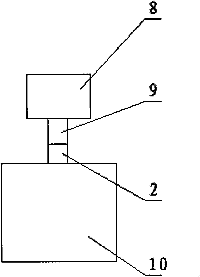
[0010] exist figure 1 In the illustrated embodiment of the invention, a movable shaft 2 , an upper coil 4 , a lower coil 6 and a permanent magnet 3 are included. The movable shaft 2 is located on the axis of the upper coil 4 and the lower coil 6 . The upper coil 4 and the lower coil 6 are coaxially placed in the annular cylinder 5 . Each coil has an inner diameter of 50mm, an outer diameter of 98mm, and a height of 28mm, and the two coils are coaxially arranged on the upper and lower parts of the cylinder. The cylinder i...


PUM


Abstract

The invention relates to an operating mechanism for a medium-high voltage distribution line circuit breaker, belonging to electrical equipment. The permanent-magnet operating mechanism comprises a movable shaft, coils and a permanent magnet, wherein the movable shaft is positioned at the axial lines of the coils; the permanent magnet is circular and fixed on the movable shaft, and the outer diameter of the permanent magnet is less than the inner diameter of each coil; the number of the coils is at least two; and the coils are coaxially arranged in a circular cylinder body. On the basis of the structure, the invention can also have the structure that the cylinder body can conduct magnetism and has an axial section which is in a hollow H shape, and both ends of the cylinder body are provided with an upper cover plate and a lower bottom plate which both can conduct magnetism. The invention strengthens the interaction among magnetic fields, increases the utilization ratio of the magnetic fields, realizes the idle work of the on-off state of the circuit breaker operating mechanism, optimizes the on-off state characteristics of the circuit breaker operating mechanism, enhances the controllability of the circuit breaker, has the advantages of simple structure and low cost, and enhances the reliability of the whole circuit breaker.

Description

Technical field [0001] The invention relates to an operating mechanism for a circuit breaker of medium and high voltage distribution lines, which belongs to electrical equipment. Background technique [0002] At present, in the power industry at home and abroad, the operating mechanism of the vacuum circuit breaker used for power distribution lines mainly uses the principle of electromagnetic field to attract ferromagnetic materials, that is, by energizing the coils near the upper or lower ends of the movable shaft to attract and fix the ferromagnetic materials. The armature on the movable shaft drives the movable part to move up or down to realize the closing or opening of the circuit breaker. Since this kind of operating mechanism uses the attraction force of the electromagnet to the ferromagnetic material to drive the moving parts to move, the moving parts can only be accelerated and cannot be decelerated during the movement process. Reactive power maintenance in the clo...

Claims


Application Information

Patent Timeline
Patent Type & Authority Applications(China)
IPC IPC(8): H01H3/28H01H33/666
Inventor 王法宋澜
Owner UNIV OF SCI & TECH OF CHINA
Why Eureka
Try Eureka