Embedded standby energy-saving method and device

A standby energy-saving, embedded technology, applied in electric controllers, controllers with pulse train output signals, etc., can solve the problems of standby power consumption and energy waste of switching power supply

Inactive Publication Date: 2010-09-29
SHANGHAI UNIV
View PDF5 Cites 15 Cited by
  • Summary
  • Abstract
  • Description
  • Claims
  • Application Information

AI Technical Summary

Problems solved by technology

However, after the electrical equipment is turned off, the switching p

Method used


Image

  • Embedded standby energy-saving method and device
  • Embedded standby energy-saving method and device
  • Embedded standby energy-saving method and device

Examples


Embodiment 1

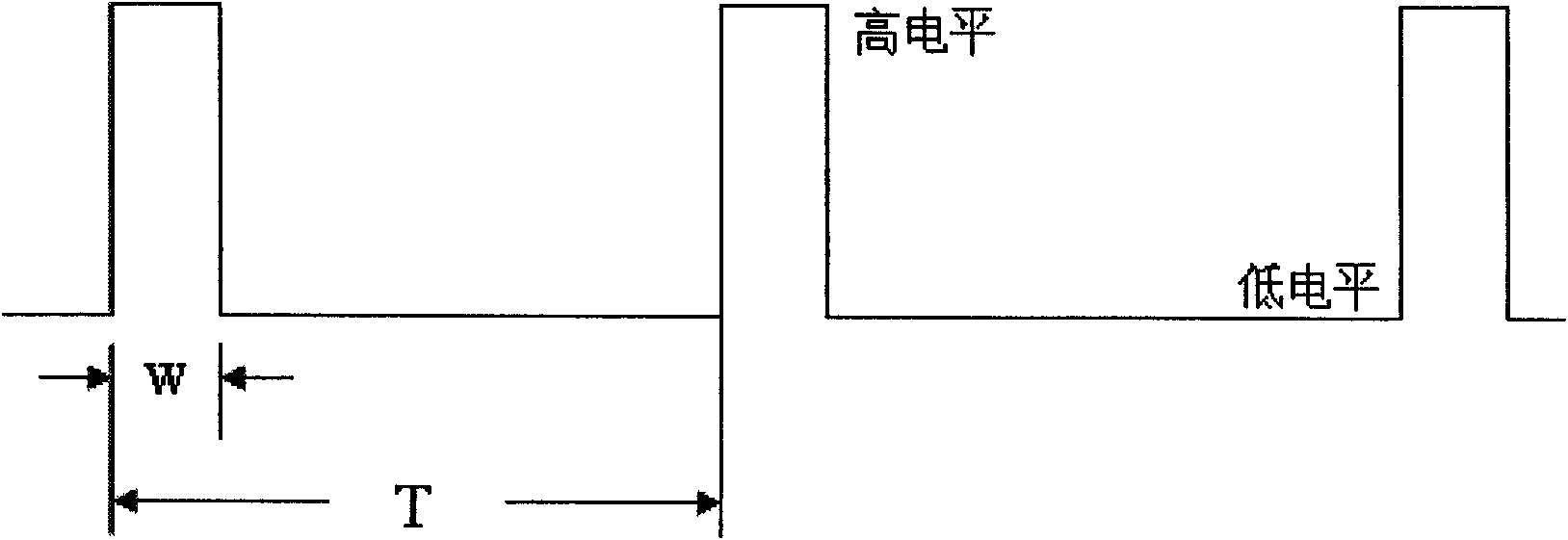
[0018] Embodiment one: see figure 1 , figure 2 , image 3 and Figure 4 , this embedded standby energy-saving method is characterized in that a control circuit 4, an electronic switch 2 and a sensor 3 are used to realize intermittent power supply and synchronous detection of the standby state of the electrical equipment 5, and when the electrical equipment 5 is powered on and started and works normally , the sensor 3 transforms the detected power supply current into a signal level of a corresponding magnitude and inputs it to the control circuit 4. This signal level is greater than the discrimination threshold level 7, and is converted into a signal whose amplitude remains constant by the control circuit. The pulse signal is output to the electronic switch, and the electronic switch is kept on to provide normal and continuous power supply to the electrical equipment 5 .

Embodiment 2

[0019] Embodiment 2: This embodiment is basically the same as Embodiment 1, and the special features are as follows:

[0020] 1. Active power devices such as MOSFETs, IGBTs or bidirectional thyristors are used to form contactless electronic switches that turn on and off the path

[0021] 2; Eliminate the shortcomings of short electrolytic corrosion life and slow response speed of relay switch contacts. The control terminal 6 turns on active power devices such as MOSFETs, IGBTs or bidirectional thyristors, that is, the electronic switch 2 is turned on; the control terminal 6 turns off the active power devices, that is, the electronic switch 2 is turned off.

[0022] 2. Use devices such as current transformers, Hall ICs, or sampling resistors to form a sensor 3 for real-time detection of the current of electrical equipment.

[0023] 3. After the electronic switch 2 and the sensor 3 are connected in series, they are embedded between the electrical equipment 5 and the mains 1 thr...

Embodiment 3

[0029] Embodiment three: see figure 2 , the embedded energy-saving standby device includes an electronic switch 2, the commercial power 1 is connected to the electrical equipment 5 including the switching power supply after passing through the electronic switch 2 and a sensor 3, and the output terminal of the sensor 3 is connected through a control circuit 4 The control terminal 6 of the electronic switch 2 .


PUM


Abstract

The invention relates to an embedded standby energy-saving method and an embedded standby energy-saving device. In the method, a control circuit, an electronic switch and a sensor are embedded between electric equipment and an electric supply through a distribution socket or an electricity cable; the control circuit, the electronic switch and the sensor realize intermittent power supply and synchronous detection when the electric equipment is in a standby state; when the electric equipment is electrified and normally works, the sensor converts the detected supply current into a signal level with the same size and inputs the signal level to the control circuit; if the signal level is more than a screening threshold level, the control circuit converts the signal level into a pulse signal with constant amplitude and outputs the pulse signal into the electronic switch; and then the electronic switch is maintained to be turned on and normally and continuously supplies power to the electric equipment. In the device, the electric supply is connected with the electric equipment with a switch power supply through the electronic switch and the sensor, and the output end of the sensor is connected with the control end of the electronic switch through the control circuit. The method and the device can conveniently realize standby energy conservation between the electric equipment and the electric supply; and the device has the characteristics of small volume, light weight, reliability, low price and long service life.

Description

Technical field: [0001] This patent relates to a method and device for saving standby energy consumption of switching power supplies in electrical equipment. Widely used in various electrical equipment such as desktop computers, computer peripherals, air conditioners, and televisions, it can save standby power consumption after the electrical equipment is turned off. Background technique: [0002] Switching power supply has many advantages such as high conversion efficiency, small size, light weight, etc., and is currently selected as the power supply for all electrical equipment. However, after the electrical equipment is turned off, the switching power supply has standby power consumption, resulting in waste of energy. However, this part of energy must be provided to ensure the restart of the electrical equipment after shutdown. Therefore, how to minimize standby power consumption, adapt to low-carbon environmental protection and comply with the requirements of various e...

Claims


Application Information

Patent Timeline
IPC IPC(8): G05B11/26
Inventor 程东方张齐冉峰沈伟星冯旭
Owner SHANGHAI UNIV
Why Eureka
Try Eureka