
Grabbing device for moving wall/floor tiles

A technology for grabbing devices and wall and floor tiles, which is applied in the direction of manipulators, chucks, manufacturing tools, etc., and can solve the problems of poor placement adaptability, complex structure of the grabbing mechanism, and many grabbing actions.

Active Publication Date: 2010-09-29
佛山市鼎吉包装技术有限公司
View PDF7 Cites 4 Cited by
  • Summary
  • Abstract
  • Description
  • Claims
  • Application Information

AI Technical Summary

Problems solved by technology

[0002] In the production of ceramic or natural stone wall and floor tiles, there are requirements for the production process of wall and floor tiles off-line-storage-on-line; usually, the wall and floor tiles after offline are placed on the brick frame, currently in the ceramic or natural stone wall and floor tiles During the production process, manual upper and lower brick operations are usually used, that is, the bricks are manually removed from the production line and leaned vertically on the brick frame; or the reverse operation is performed. Due to the harsh environment on site, the labor intensity of the workers is relatively high.
There are also some that use mechanical grabbing, but this kind of grabbing mechanism has a complex structure, many grabbing actions, and has high requirements for brick frames, and poor adaptability to brick placement. Before grabbing, special devices need to be used to place bricks Therefore, the ceramic and stone industry has a strong demand for mechanized automatic brick-loading equipment with simple structure and strong on-site adaptability

Method used


Image

  • Grabbing device for moving wall/floor tiles
  • Grabbing device for moving wall/floor tiles
  • Grabbing device for moving wall/floor tiles

Examples


Embodiment Construction

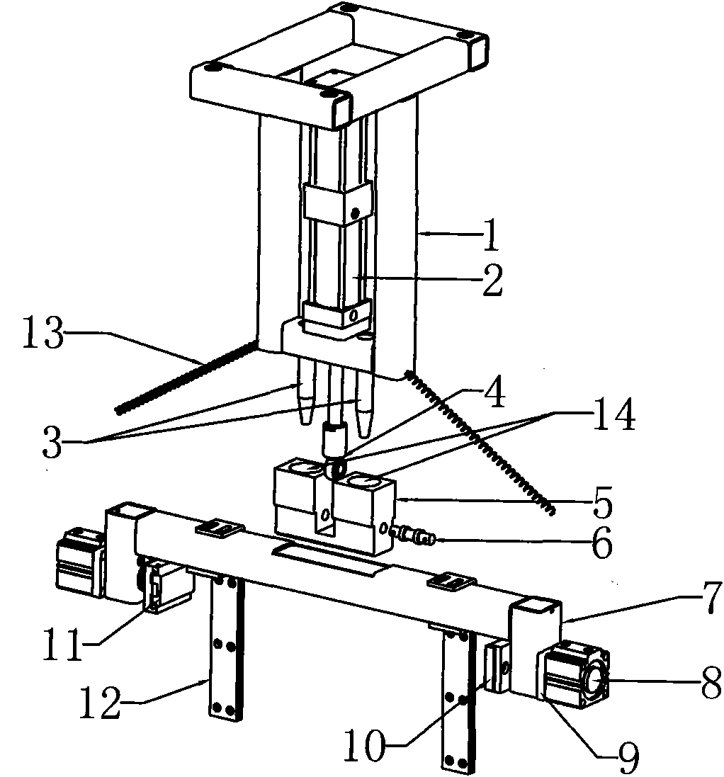
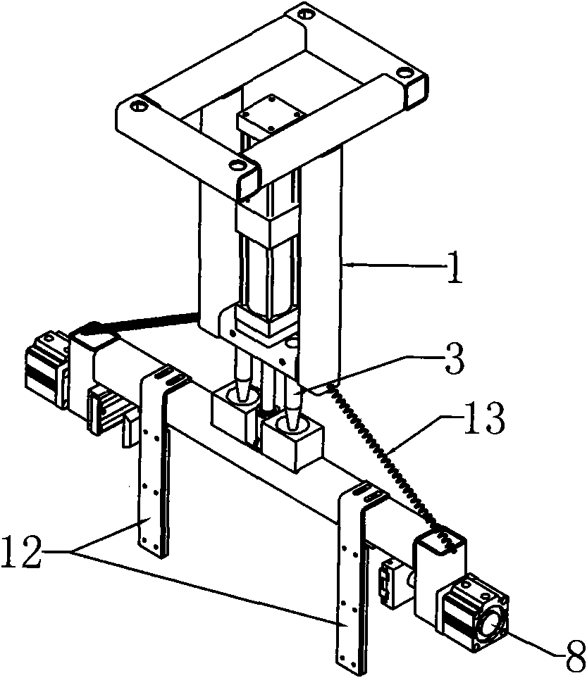
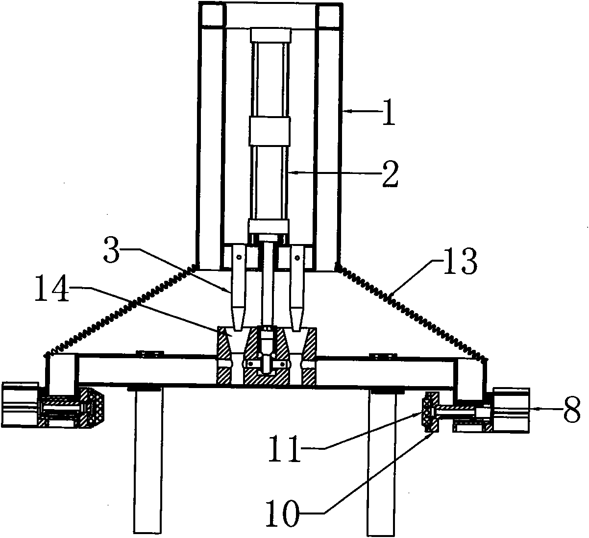
[0015] Attached below figure 1 To attach Figure 4 To further illustrate the present invention, the preferred embodiment of the present invention is: a grabbing device for transferring wall and floor tiles described in this embodiment, which includes an organic base 1, an extraction cylinder 2, a limit pin 3, a fish eye Joint 4, connecting block 5, hinged shaft 6, grasping frame 7, grasping cylinder 8, grasping claw 10, ruler plate 12, return spring 13. Wherein, the cylinder body of the extracting cylinder 2 is fixed in the machine base 1, and the fish-eye joint 4 is installed on the piston rod of the extracting cylinder 2, and is hinged with the connecting block 5 in the gripping frame 7 through the hinge shaft 6. During work, the extracting cylinder 2 drives the grasping frame 7 to descend to the top of the wall and floor tiles that need to be grasped. Support 1 lower end is provided with back-moving spring 13, and back-moving spring 13 is two, is positioned at support 1 a...


PUM


Abstract

The invention provides a grabbing device for moving wall / floor tiles, which comprises a machine stand, an extraction cylinder, a limit pin, a grasp frame, a grasp cylinder, a grasp claw, a gauge board and a reset spring, wherein the body of the extraction cylinder is fixed in the machine stand; a fish eye joint is arranged on a piston rod of the extraction cylinder and is hinged with a connection block in the grasp frame through a hinging shaft; the limit pin is arranged at the lower end of the machine stand; the connection block is provided with a limit hole matched with the limit pin; one end of the reset spring is connected with the lower end of the machine stand, and the other end of the reset spring is connected with the grasp frame; the grasp cylinder is arranged at two end s of the grasp frame through a grasp cylinder seat; the piston rod of the grasp cylinder is connected with the grasp claw; and the gauge board is positioned on the grasp frame connected with two sides of the connection block. As the grabbing device in the scheme grabs from the upward side of wall / floor tiles and fully utilizes the characteristic that the upper edges of the wall / floor tiles are naturally together and tight when the wall / floor tiles are vertically placed and stacked, the grabbing device does not need to use special tightening devices, greatly simplifies the structure thereof, and is stronger in on-site adaptability in the grabbing process.

Description

Technical field: [0001] The invention relates to the technical field of wall and floor tile packaging equipment, in particular to a grabbing device for transferring wall and floor tiles. Background technique: [0002] In the production of ceramic or natural stone wall and floor tiles, there are requirements for the production process of wall and floor tiles off-line-storage-on-line; usually, the wall and floor tiles after offline are placed on the brick frame, currently in the ceramic or natural stone wall and floor tiles During the production process, manual upper and lower brick operations are usually used, that is, the bricks are manually removed from the production line and leaned vertically on the brick frame; or the reverse operation is performed. Due to the harsh environment on site, the labor intensity of the workers is relatively high. There are also some that use mechanical grabbing, but this kind of grabbing mechanism has a complex structure, many grabbing actions...

Claims


Application Information

Patent Timeline
Patent Type & Authority Applications(China)
IPC IPC(8): B25J15/00
Inventor 彭智勇
Owner 佛山市鼎吉包装技术有限公司
Learn More